Bereiten Sie das ONU-Webmanagement für die Anmeldung vor Bevor Sie die ONU,Sie sollten sich vergewissern, dass die Verbindung zwischen der ONU und Ihrem PC normal ist. Schritt 1 Konfigurieren Sie die IP-Adresse Ihres PCs auf 192.168.1.x(2~254), die Subnetzmaske lautet 255.255.255.0 Schritt 2 Ping IP-Adresse des ONU (Standardadresse ist 192.168.1.1). Wenn der PC die richtige Antwort auf den Ping-Befehl erhält, bedeutet dies, dass die Verbindung zwischen PC und ONU ist normal.
Anmeldung ONU
Schritt 1 Öffnen Sie den Explorer-Browser und geben Sie die IP-Adresse ein: http://192.168.1.1.
(ONU Standard-IP)
Schritt 2 Für die Anmeldung benötigen Sie einen Benutzernamen und ein Kennwort, die standardmäßig auf dem Etikett des Geräts angegeben sind. ONU Der Standard-Benutzername und das Passwort des Administrators lautet “admin" und "admin"
( wählen Sie hier die Anmeldesprache)
Gerätestatus
Auf dieser Seite werden der aktuelle Status und einige grundlegende Einstellungen des Geräts angezeigt.
IPv6-Status
Diese Seite zeigt den aktuellen Systemstatus von IPv6 an.
PON-Status
Diese Seite zeigt den aktuellen Systemstatus von PON an.
ARP-Tabelle
Diese Tabelle zeigt eine Liste der gelernten MAC-Adressen.
PON WAN
Diese Seite dient zur Konfiguration der Parameter für PONWAN
LAN-Schnittstelleneinstellungen
Diese Seite dient der Konfiguration der LAN-Schnittstelle Ihres Geräts. Hier können Sie die Einstellungen für IP-Adressen, Subnetzmaske, etc. ändern.
IP/Port-Filterung
Einträge in dieser Tabelle werden verwendet, um bestimmte Arten von Datenpaketen durch das Gateway zu beschränken. Die Verwendung solcher Filter kann hilfreich sein, um Ihr lokales Netzwerk zu sichern oder einzuschränken.
MAC-Filterung
Die Einträge in dieser Tabelle werden verwendet, um bestimmte Arten von Datenpaketen aus Ihrem lokalen Netzwerk über das Gateway ins Internet zu beschränken. Die Verwendung solcher Filter kann hilfreich sein, um Ihr lokales Netzwerk zu sichern oder einzuschränken.
ACL-Konfiguration
Diese Seite dient zur Konfiguration der IP-Adresse für die Zugriffskontrollliste. Wenn ACL aktiviert ist, kann nur die IP-Adresse in der ACL-Tabelle auf CPE zugreifen. Hier können Sie die IP-Adresse hinzufügen/löschen.
Portweiterleitung
Mit den Einträgen in dieser Tabelle können Sie allgemeine Netzwerkdienste automatisch auf einen bestimmten Rechner hinter der NAT-Firewall umleiten. Diese Einstellungen sind nur erforderlich, wenn Sie eine Art von Server wie einen Webserver oder Mailserver im privaten lokalen Netzwerk hinter der NAT-Firewall des Gateways hosten möchten.
DMZ-Konfiguration
Eine entmilitarisierte Zone wird verwendet, um Internet-Dienste anzubieten, ohne den unbefugten Zugang zu seinem lokalen privaten Netzwerk zu opfern. In der Regel enthält der DMZ-Host Geräte, die für den Internetverkehr zugänglich sind, wie Web- (HTTP-) Server, FTP-Server, SMTP- (E-Mail-) Server und DNS-Server.
RoutingKonfiguration
Diese Seite dient zur Konfiguration der Routing-Informationen. Hier können Sie IP-Routen hinzufügen/löschen.
RIP-Konfiguration
Aktivieren Sie RIP, wenn Sie dieses Gerät als RIP-fähiges Gerät für die Kommunikation mit anderen verwenden, die das Routing Information Protocol verwenden. Auf dieser Seite können Sie die Schnittstellen Ihres Geräts auswählen, die RIP verwenden, sowie die Version des verwendeten Protokolls.
ZeitzonenKonfiguration
Sie können die Systemzeit durch Synchronisierung mit einem öffentlichen Zeitserver über das Internet beibehalten.
IPv6-Konfiguration
Auf dieser Seite kann IPv6 aktiviert/deaktiviert werden
RADVD-Konfiguration
Diese Seite dient zur Einrichtung der RADVD-Konfiguration Ihres Geräts.
DHCPv6-Einstellungen
Diese Seite dient zur Konfiguration von DHCPv6-Server und DHCPv6-Relay.
IPv6 Statische RoutingKonfiguration
Diese Seite dient der Konfiguration der statischen IPv6-Routen. Hier können Sie statische IP-Routen hinzufügen/löschen.
IPv6 IP/Port-Filterung
Einträge in dieser Tabelle werden verwendet, um bestimmte Arten von Datenpaketen durch das Gateway zu beschränken. Die Verwendung solcher Filter kann hilfreich sein, um Ihr lokales Netzwerk zu sichern oder einzuschränken.
IPv6 IP/Port-Filterung
Einträge in dieser Tabelle werden verwendet, um bestimmte Arten von Datenpaketen durch das Gateway zu beschränken. Die Verwendung solcher Filter kann hilfreich sein, um Ihr lokales Netzwerk zu sichern oder einzuschränken.
Ping-Diagnose
Diese Seite wird verwendet, um ICMP ECHO_REQUEST-Pakete an den Netzwerk-Host zu senden. Das Diagnoseergebnis wird dann angezeigt.
GPON-Einstellungen
Auf dieser Seite können Sie die Parameter für Ihren GPON-Netzzugang konfigurieren.
OMCIInfo
Diagnostik - Schleifenerkennung
Diese Seite dient zur Konfiguration der Schleifenerkennungsparameter. Hier können Sie die Einstellungen ändern oder den Status der Schleifenerkennung anzeigen.
Überbrückungskonfiguration
Diese Seite dient zur Konfiguration der Bridge-Parameter. Hier können Sie die Einstellungen ändern oder einige Informationen über die Bridge und die angeschlossenen Ports anzeigen.
Neustart-Timer
Nach Ablauf der eingestellten Zeit wird es neu gestartet!
Einstellungen sichern und wiederherstellen
Auf dieser Seite können Sie die aktuellen Einstellungen in einer Datei sichern oder die Einstellungen aus einer zuvor gespeicherten Datei wiederherstellen. Außerdem können Sie die aktuellen Einstellungen auf die Werkseinstellungen zurücksetzen.
Passwort-Konfiguration
Auf dieser Seite können Sie das Konto für den Zugriff auf den Webserver Ihres Geräts festlegen. Wenn Sie einen leeren Benutzernamen und ein leeres Passwort eingeben, wird der Schutz deaktiviert.
Interface-Statistiken
Diese Seite zeigt die Paketstatistiken für die Übertragung und den Empfang in Bezug auf die Netzwerkschnittstelle an.
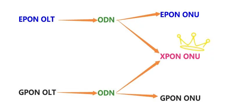
Passive optische Netze (PONs) spielen eine wichtige Rolle bei der Bereitstellung des Zugangs zu Glasfasernetzen für Endkunden. Sie ermöglichen den Tra...
Die Zollgebühren liegen in der Verantwortung des Kunden, aber die Standardlogistik unterstützt DDP in die meisten Länder, zollfrei wie US, DE, UK, CA, FR, IT, PL, AT, JP...
Wir sehen, dass du dich in folgendem Land befindest: Vereinigtes Königreich. Wir haben unsere Preise entsprechend auf Pfund Sterling aktualisiert, um dir ein besseres Einkaufserlebnis zu bieten. Stattdessen Vereinigte Staaten (US) Dollar verwenden.Ausblenden


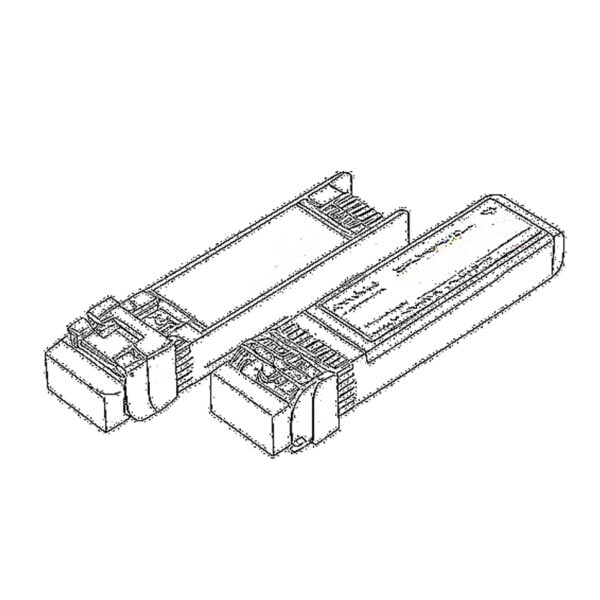 SFP/SFP+ (1G/2.5G/5G/10G)
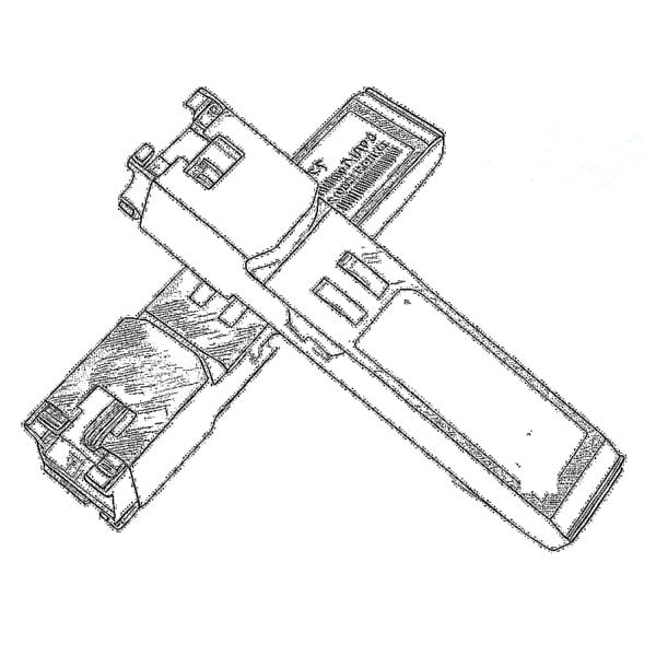 SFP-T (1G/2.5G/10G)
 AOC-Kabel 10G/25G/40G/100G
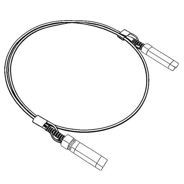 DAC-Kabel 10G/25G/40G/100G
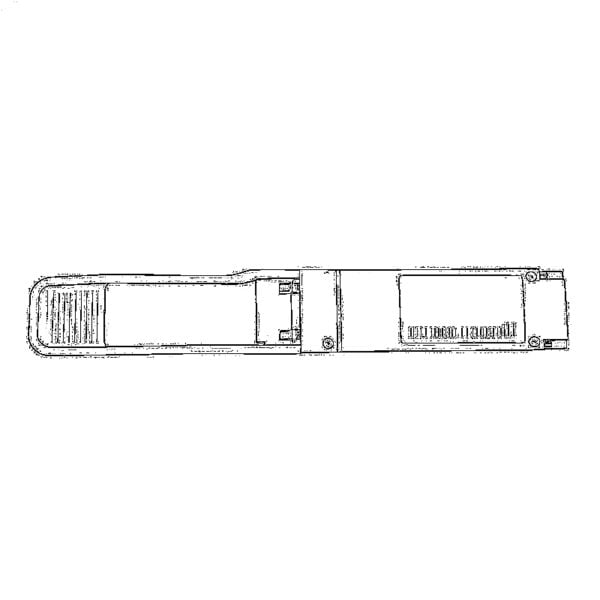 QSFP28 QSFP+ SFP28 100G/40G/25G
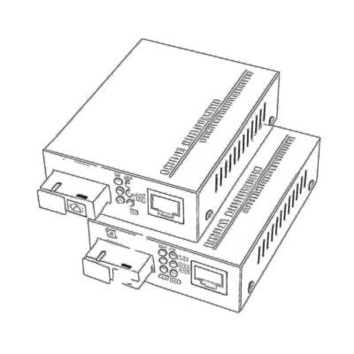 Kupfer-Glasfaser-Medienkonverter
 Glasfaser-Medienkonverter PCBA-Platine
 OEO Fiber Medienkonverter
 Seriell-Glasfaser-Medienkonverter
 Video zu Glasfaser Medienkonverter
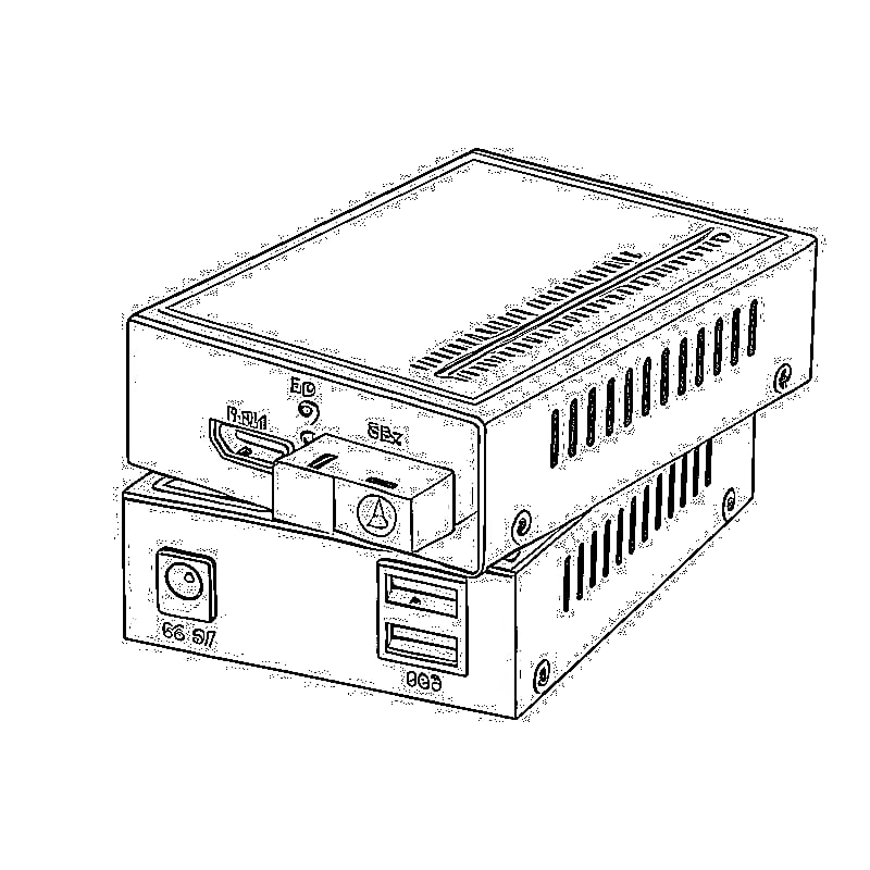
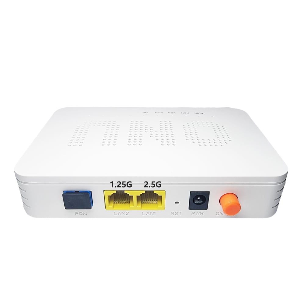
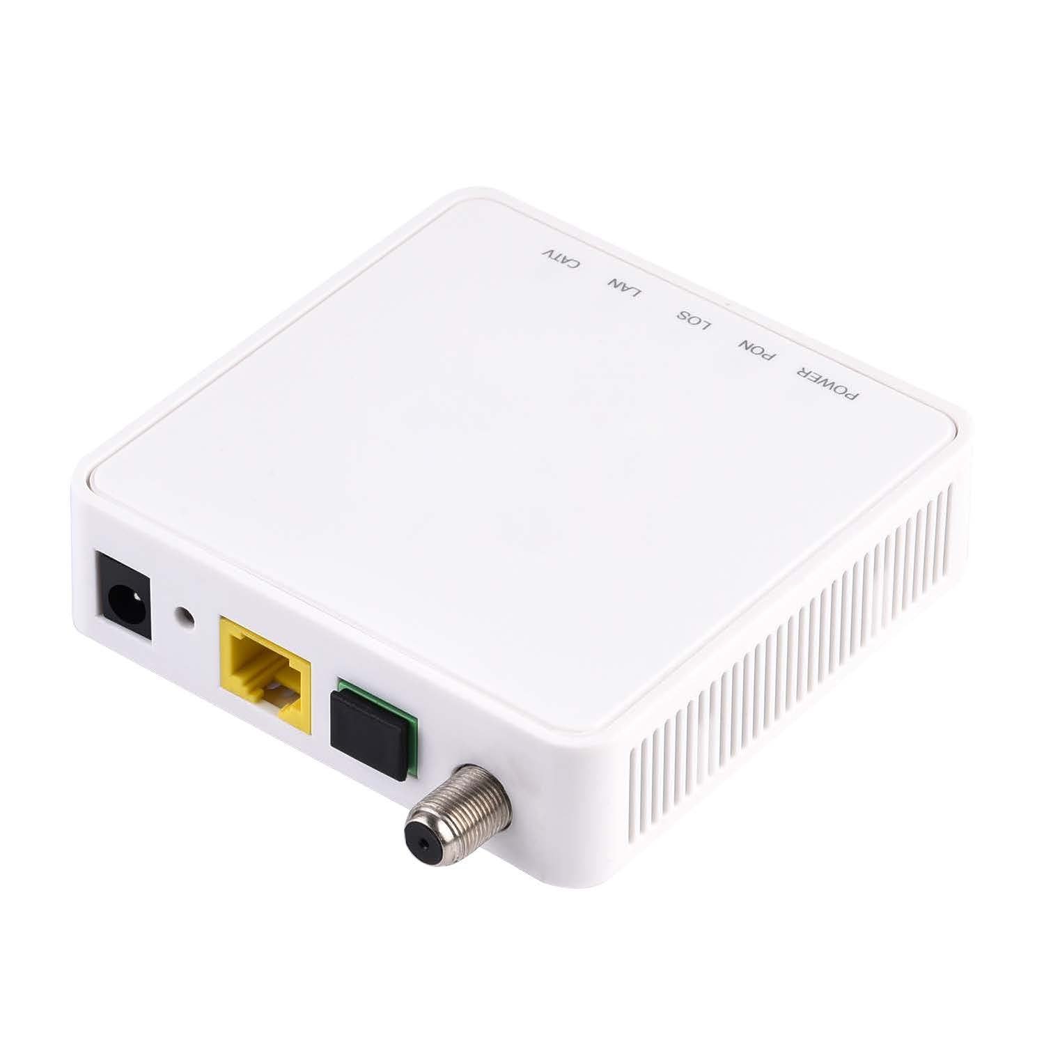
 1000M GPON/EPON ONU
 10G EPON ONU/XG-PON/XGS-PON
 2.5G GPON/XPON STICK SFP ONU
 POE GPON/EPON ONU
 Drahtloser GPON/EPON ONT
 EPON OLT
 GPON OLT
 SFP-PON-Modul
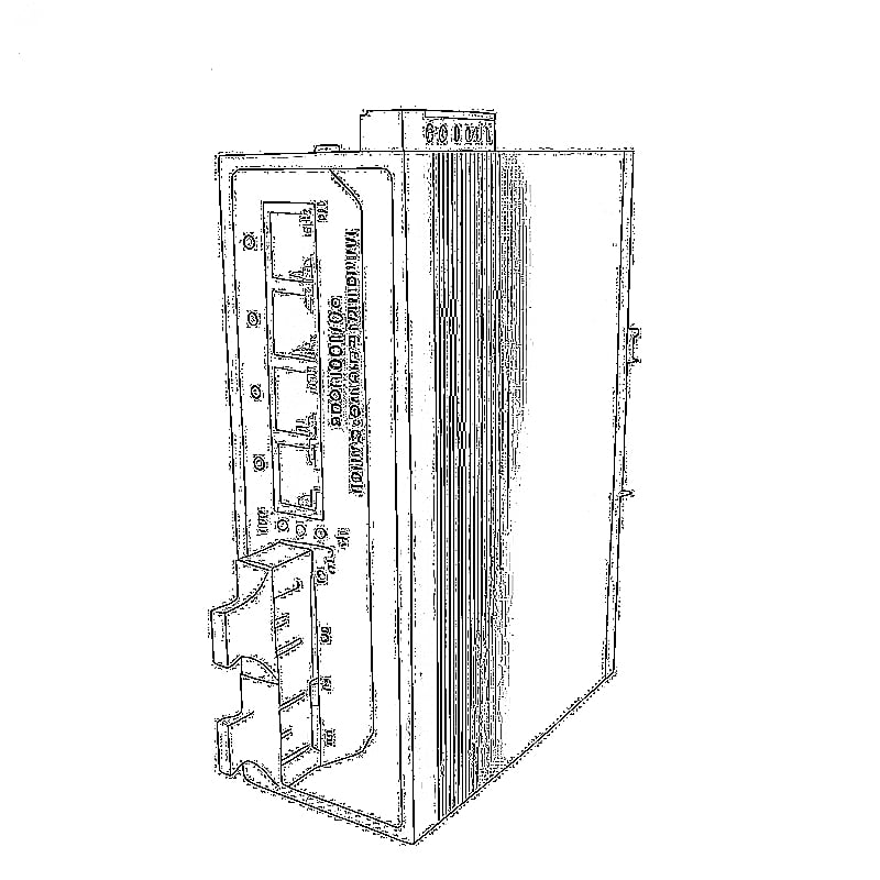
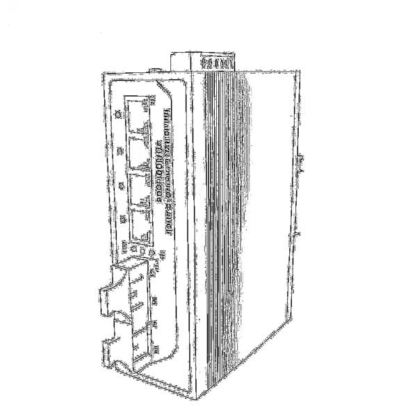 Industrielle Schalter
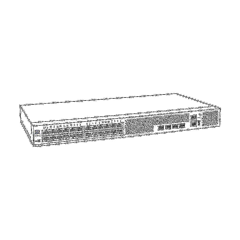
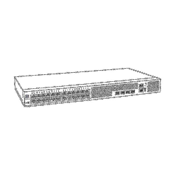 Managed Switches
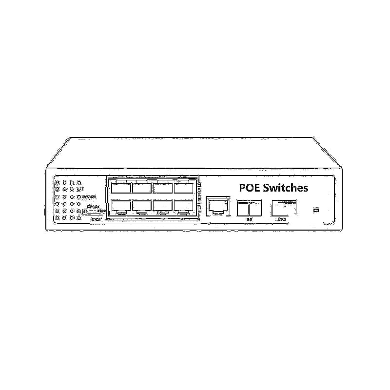
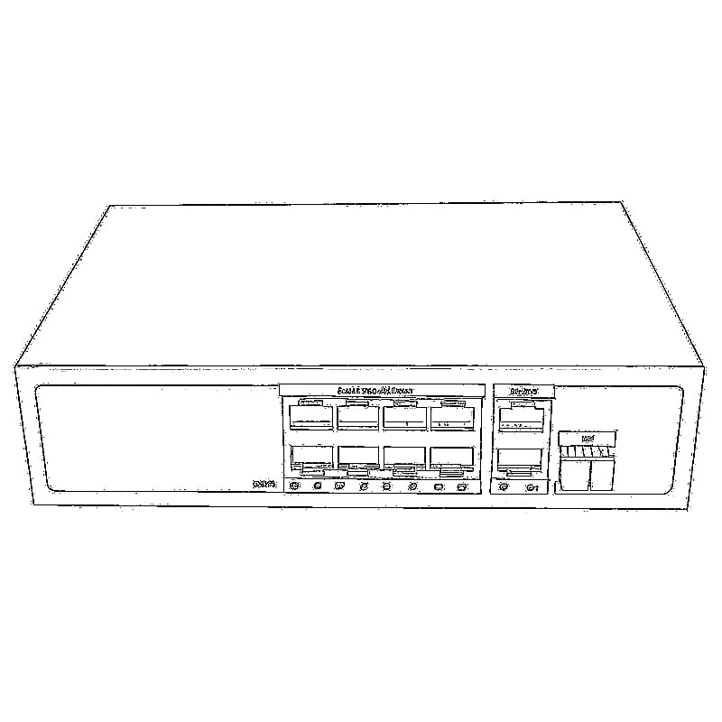
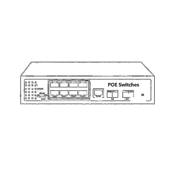 POE-Schalter
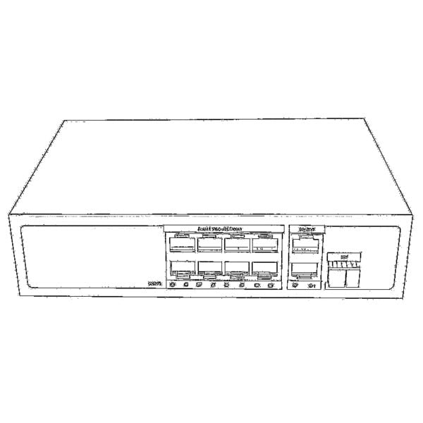 Unmanaged Switches
 MTP/MPO-Glasfaserkabel
 Faseroptische Kassetten
 Fiber Optic Loopback
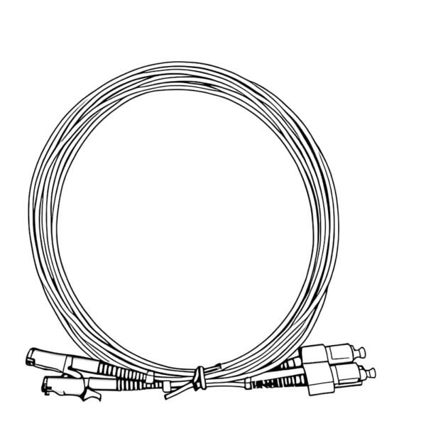
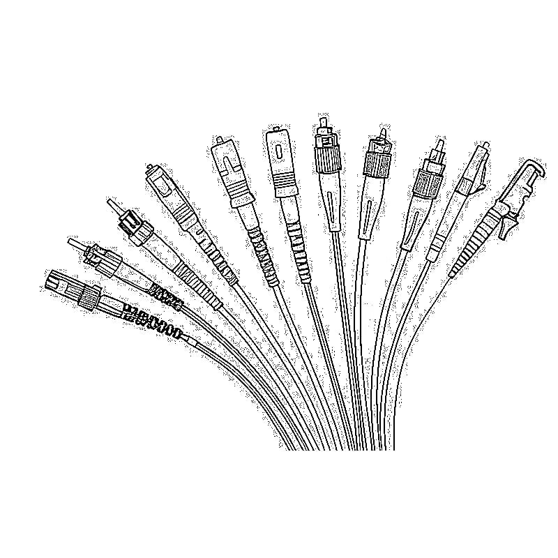
 Lichtwellenleiterkabel und Faserpigtails
 Optische Splitter und Splitterbox
 Faserflansch-Verbinder
 Optische Adapter
 Optisches Dämpfungsglied
 Schnellanschluss und Anschlussfeld
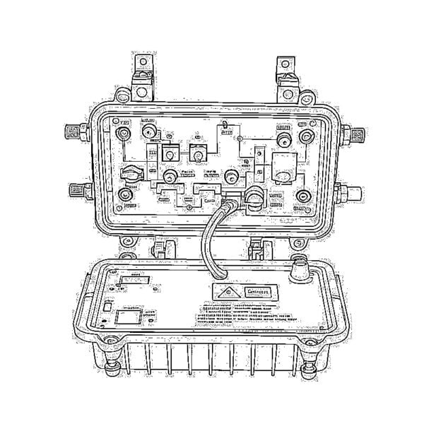
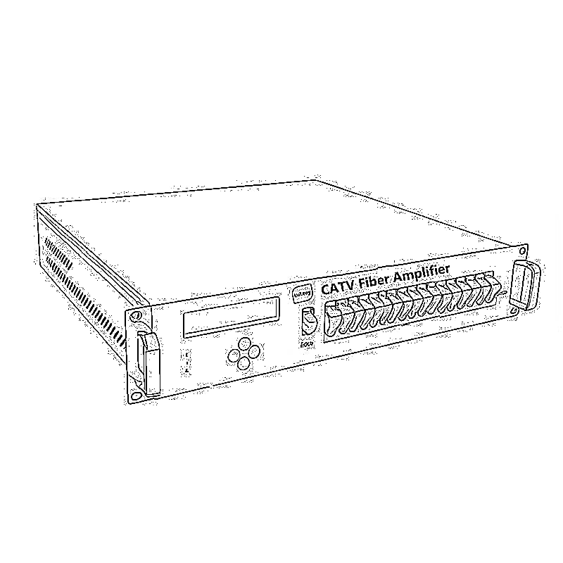
 CATV-Verstärker
 Optischer CATV-Empfänger
 Visuelle Fehlersuche
 OTDR
OTDR Optischer Leistungsmesser
 Faseroptische Kennung
 Faseroptische Reiniger
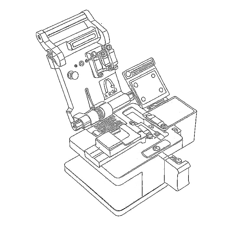
 Fiber Cleavers & Fiber Strippers
 Werkzeuge aus Kupfer