تخفيضات «الجمعة السوداء»: خصم 10% على الطلبات التي تزيد قيمتها عن 100 دولار | تقع مسؤولية الرسوم الجمركية على عاتق العملاء، لكننا نقدم دعمًا لوجستيًا قياسيًا بنظام «تسليم إلى الوجهة» (DDP) إلى معظم البلدان، مع إعفاء من الرسوم الجمركية، مثل الولايات المتحدة، وألمانيا، والمملكة المتحدة، وكندا، وفرنسا، وإيطاليا، وبولندا، والنمسا، واليابان...

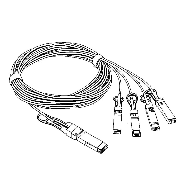
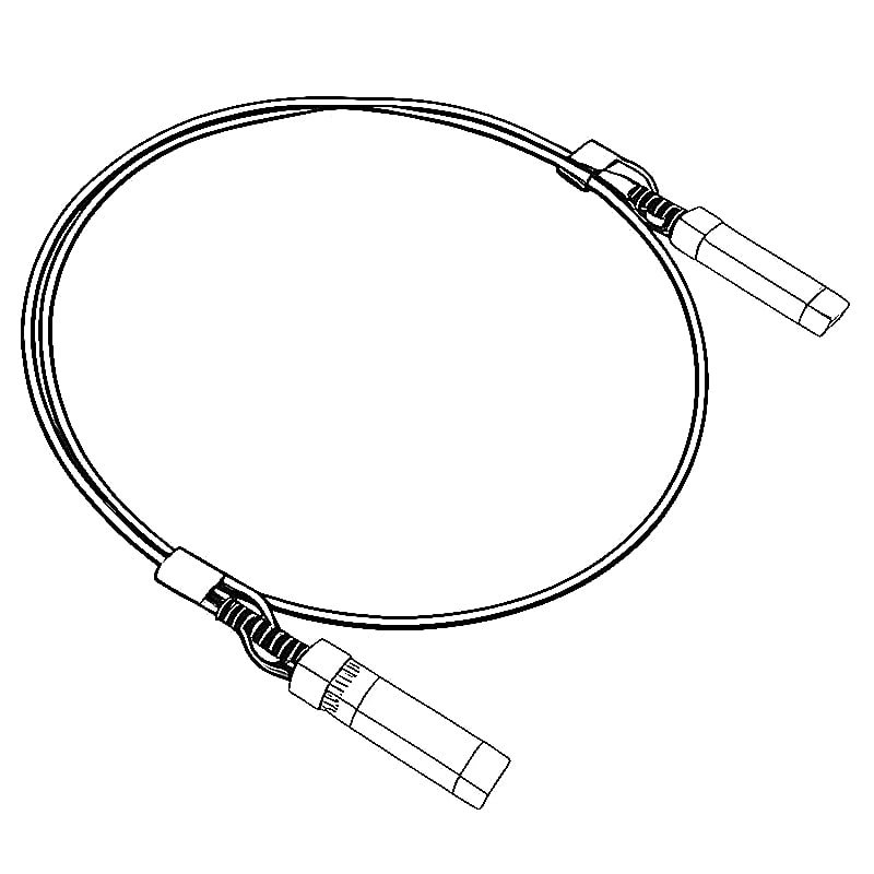

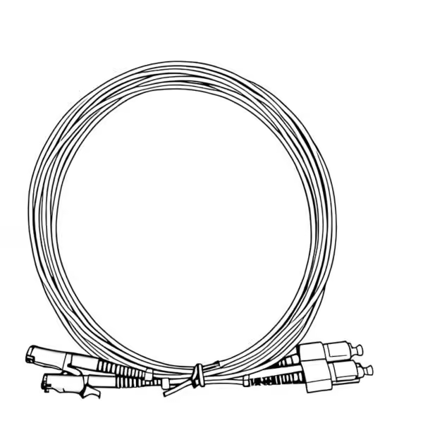
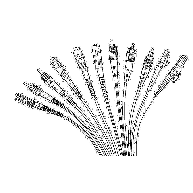
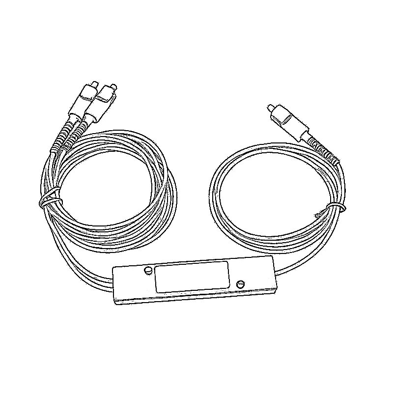
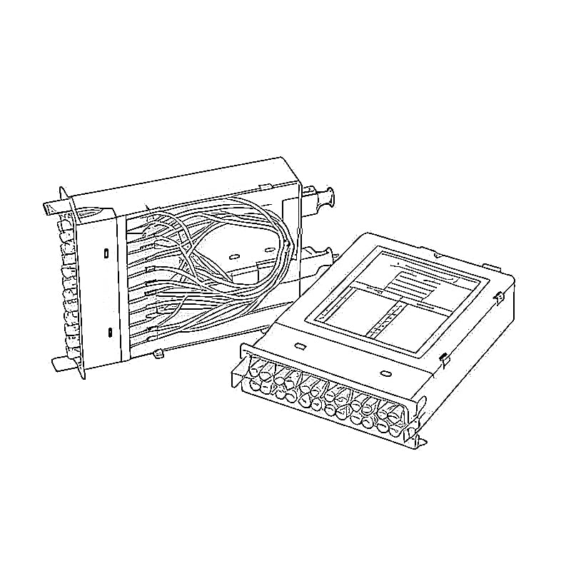
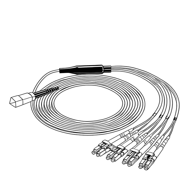
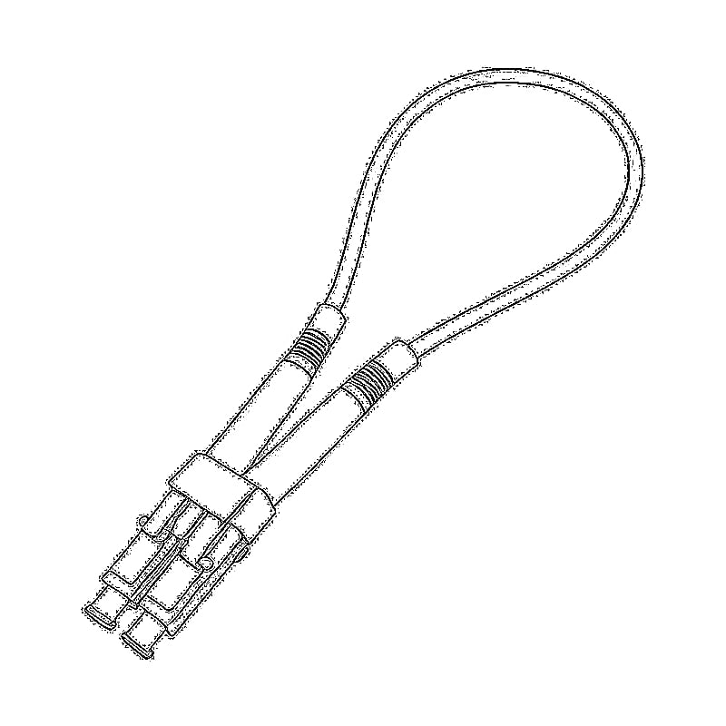
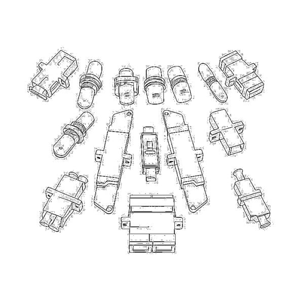
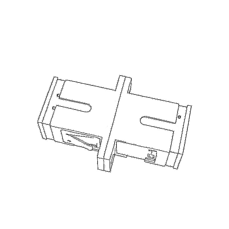


Custom Trunk & Breakout Cables for Data Centers, Telecom and High-Density Fiber Networks

Custom MPO Cable solutions for OS2, OM3 and OM4 trunk and breakout assemblies, with configurable fiber counts, connectors, polarity and lengths.
Build a fiber cabling system that matches your actual network layout instead of adapting your equipment to a fixed cable configuration.
Luleey provides MPO/MTP trunk cables and MPO-to-LC, SC and FC breakout assemblies for data centers, enterprise networks, optical distribution frames, telecom systems and custom fiber projects.
Flexible Configuration | Factory-Terminated Assemblies | Optical Performance Testing
Explore MPO/MTP Cables | Request Custom Cable Configuration
MPO/MTP Fiber Cabling Overview
A custom MPO/MTP fiber cabling system combines multiple optical fibers into high-density multi-fiber connectors, making it easier to connect, distribute and manage fiber links across network equipment and patching infrastructure.
Instead of installing numerous individual patch cords throughout a data center or telecom cabinet, MPO/MTP assemblies allow groups of fibers to be routed through compact trunk cables and distributed to the required interfaces.
Luleey offers two main cable configurations:
MPO/MTP to MPO/MTP Trunk Cables
Designed for high-density backbone connections between racks, fiber patch panels, cassettes and compatible optical equipment.
MPO/MTP to LC / SC / FC Breakout Cables
Designed to distribute one multi-fiber MPO/MTP interface into individual LC, SC or FC connectors for equipment connections, optical distribution and fiber patching.
Available configurations include OS2 single-mode and OM3/OM4 multimode fiber, with customizable connector types, fiber counts, polarity and cable lengths.
Two Main MPO/MTP Cabling Solutions
1. MPO/MTP to MPO/MTP Trunk Cable
High-Density Backbone Cabling
MPO/MTP trunk cables provide a direct multi-fiber connection between two MPO/MTP interfaces.
They are commonly used between fiber patch panels, equipment racks, data center rows and optical distribution systems.
A single MPO/MTP trunk assembly can replace several individual long patch cords, helping organize cables and simplify the installation of high-density fiber infrastructure.
Typical Configuration
Network Equipment / Patch Panel
↓
MPO/MTP Connector
↓
OS2 / OM3 / OM4 Fiber Trunk
↓
MPO/MTP Connector
↓
Remote Patch Panel / Equipment
Key Benefits
- High-density multi-fiber connectivity
- Reduced cable congestion
- Faster deployment of pre-terminated cabling
- Male or female MPO/MTP connector options
- Application-specific APC or UPC polishing
- Type A, Type B and Type C polarity options where applicable
- Multiple cable lengths
- Suitable for structured backbone cabling
Common Applications: Data center backbone, enterprise fiber infrastructure, rack-to-rack connections, network equipment rooms and optical patching systems.
2. MPO/MTP to LC / SC / FC Breakout Cable
Flexible Fiber Distribution and Equipment Connectivity
An MPO/MTP breakout cable, also called an MPO fanout cable, converts one multi-fiber MPO/MTP interface into multiple individual optical connectors.
It is useful when a high-density backbone must connect to optical transceivers, patch panels, test equipment, telecom interfaces or distribution frames that use conventional fiber connectors.
Typical Configuration
MPO/MTP Backbone
↓
MPO/MTP Connector
↓
Fiber Fanout Assembly
↓
Individual LC / SC / FC Connectors
↓
Network Equipment / ODF / Optical Test Equipment
Available Breakout Types
| Configuration | تطبيق نموذجي |
|---|---|
| MPO to LC/UPC | Data center switches, optical transceivers and fiber patching |
| MPO to SC/UPC | Enterprise networks and optical distribution |
| MPO to SC/APC | FTTH/PON distribution infrastructure and reflection-sensitive links |
| MPO to FC/UPC | Telecom equipment and optical measurement systems |
| MPO to FC/APC | Optical test equipment, CATV and low-reflection single-mode systems |
Each breakout assembly can be configured according to the required fiber count, connector interface, polishing type and channel mapping.
Custom MPO Cable Configurations
Every optical network is different. The correct MPO/MTP cable depends on the equipment, fiber infrastructure and connection layout.
Luleey provides flexible configuration options for both trunk and breakout assemblies.
| Configuration Item | الخيارات المتاحة |
|---|---|
| نوع الكابل | MPO–MPO Trunk / MPO–LC / MPO–SC / MPO–FC Breakout |
| نوع الألياف | OS2 Single Mode / OM3 Multimode / OM4 Multimode |
| عدد الألياف | 8F / 12F / 16F; other counts subject to confirmation |
| MPO Gender | Male (Pinned) / Female (Unpinned) |
| MPO Polish | APC / UPC according to the mating interface |
| Breakout Polish | LC/UPC, LC/APC, SC/UPC, SC/APC, FC/UPC, FC/APC |
| Fiber Mapping | Type A / Type B / Type C / Project-Specific Mapping |
| طول الكابل | 1m / 3m / 5m / 10m / 15m / 20m / Custom |
| Cable Jacket | LSZH; other jacket requirements subject to confirmation |
| Breakout Length | Standard or custom fanout length |
| الكمية | Individual cables / Small batches / Project orders |
| Testing | Optical performance testing; project-specific documentation by agreement |
Not every combination is compatible or available as an off-the-shelf product. Special connector configurations, higher fiber counts and project-specific cable construction should be confirmed before production.
How to Choose the Right MPO/MTP Cable
Step 1 — Choose the Fiber Type
OS2 Single Mode
Designed for single-mode optical infrastructure, including telecom networks, optical distribution frames, enterprise backbone links and long-distance optical systems.
OS2 is frequently selected where single-mode equipment, low-reflection APC connectors or longer optical links are required.
OM3 Multimode
A common choice for short-distance multimode cabling in data centers, enterprise network rooms and structured fiber systems.
OM4 Multimode
Suitable for high-bandwidth multimode links where additional transmission performance margin may be required compared with OM3.
Actual supported Ethernet speed and distance depend on the optical transceivers and complete link design.
Step 2 — Choose the Fiber Count
Select the number of optical fibers according to your equipment interface and channel requirements.
| عدد الألياف | الاستخدام النموذجي |
|---|---|
| 8 ألياف | Parallel optical links and four duplex breakout connections |
| 12 ليفًا | Six duplex LC connections or other 12-fiber distribution arrangements |
| 16 Fibers | High-density 16-channel breakout and compatible 16-fiber MPO systems |
| 24 Fibers or Other | Project-specific high-density cabling, subject to confirmation |
For example, an 8-fiber MPO-to-LC breakout can provide four duplex LC connections, while a 12-fiber version can provide six duplex LC connections.
A 16-fiber MPO-to-SC/APC breakout can provide sixteen individual simplex SC/APC connections.
The physical MPO interface, ferrule arrangement and channel map must match the selected fiber count.
Step 3 — Choose Trunk or Breakout
Choose an MPO-to-MPO Trunk when both ends of the cabling system use compatible MPO/MTP connectors.
Choose an كابل توزيع MPO when one MPO/MTP interface must connect to multiple individual LC, SC or FC interfaces.
For structured data center networks, trunk and breakout assemblies may also be used together with compatible patch panels and fiber cassettes.
Step 4 — Choose MPO Male or Female
MPO/MTP connectors are available in two gender configurations.
Male (Pinned): Includes alignment guide pins.
Female (Unpinned): Does not contain guide pins.
A compatible MPO connection generally requires one pinned and one unpinned connector.
Selecting the wrong connector gender can prevent proper mating or damage the connection interface.
Check the equipment, transceiver or patch panel connector before ordering.
Step 5 — Choose APC or UPC Polishing
MPO/MTP and breakout connectors must use a polishing type compatible with the mating interface.
APC: Angled physical contact polishing, commonly selected for low-reflection single-mode optical applications.
UPC: Ultra physical contact polishing, commonly used with compatible optical equipment and multimode or single-mode cabling systems.
APC and UPC connectors have different end-face geometries and must not be directly mated.
The correct choice depends on the actual equipment interface, not simply the fiber type.
Step 6 — Confirm Fiber Polarity
Correct polarity ensures optical transmit channels connect to the corresponding receive channels throughout the complete fiber path.
Common MPO/MTP cabling arrangements include:
Type A — Straight-Through
Maintains the corresponding fiber position between both ends.
Type B — Reversed
Reverses the fiber position sequence between both ends.
Type C — Pairwise Flipped
Swaps adjacent fiber pairs within the supported cabling arrangement.
The required polarity depends on the connector format, fiber count, patch panels, cassettes, transceivers and complete network architecture.
For 16-fiber and other specialized breakout assemblies, the exact MPO-to-individual-connector mapping should be specified and confirmed before production.
Step 7 — Choose Cable and Breakout Length
Measure the actual cable routing path between equipment interfaces.
Include rack routing, cable trays, patch panels, vertical cable management and installation slack.
For breakout assemblies, also confirm the individual fanout length required for each connector group.
Custom lengths can be arranged according to project requirements.
Step 8 — Confirm the Final Configuration
Before production, verify the following:
- Fiber type and fiber count
- MPO connector gender and polish
- Breakout connector type and polish
- Exact polarity and channel mapping
- Cable length and breakout length
- Installation and jacket requirements
- Order quantity and any testing documentation requirements
MPO/MTP Solutions by Application
Data Center Backbone Cabling
Recommended: OM3 / OM4 MPO-to-MPO Trunk Cables
Modern data centers often require dense fiber connections between racks, switches, optical patch panels and network distribution areas.
MPO/MTP trunk cables help organize multi-fiber connections and simplify structured cabling deployment.
For parallel optical applications, confirm the required fiber count and MPO interface format of the transceiver.
40G and 100G Network Cabling
Recommended: Compatible OM3 / OM4 Trunk and LC Breakout Assemblies
Many 40G and 100G multimode optical systems use parallel fiber interfaces, while other transceiver types use duplex LC connectors.
MPO/MTP cables can support the required infrastructure when the fiber count, transceiver interface, polarity and optical link budget are correctly matched.
For example, a compatible 8-fiber parallel optical system may use four transmit and four receive fibers.
Not all 40G or 100G transceivers use the same MPO connector or fiber layout. Check the exact optical module specification before selecting the cable.
Telecom and Optical Distribution Frames
Recommended: OS2 MPO-to-SC/APC or MPO-to-FC/APC Breakout Cables
Telecom installations often require multiple single-mode fibers to be distributed from a high-density backbone into individual equipment ports.
An OS2 MPO breakout cable can simplify the connection between a fiber distribution system and individual SC/APC or FC/APC interfaces.
Typical applications include central offices, optical distribution frames, telecom equipment cabinets, CATV-related infrastructure and optical test systems.
غرف شبكات المؤسسات
Recommended: OM3 / OM4 MPO Trunk and MPO-to-LC Breakout
MPO/MTP cabling helps reduce cable congestion in enterprise equipment rooms and supports a structured connection between backbone fiber and equipment ports.
Breakout cables are especially useful when multiple duplex LC connections are required from a single multi-fiber trunk.
Custom Equipment and Laboratory Connections
Recommended: Project-Specific MPO Breakout Assemblies
Some optical systems use a nonstandard connector arrangement, specific channel order or individually labeled breakout fibers.
For these projects, the cable can be defined using a drawing or fiber mapping table.
This helps ensure that every breakout connector corresponds to the required MPO fiber position.
Explore Luleey MPO/MTP Cable Products
Start with an existing product configuration or use it as a reference for your custom cable requirements.
MPO/MTP Trunk Cables
8 Fiber OM3 MPO/MTP Trunk Cable
An 8-fiber multimode trunk option for compatible data center and parallel optical connections.
12 Fiber OM4 MPO/MTP Trunk Cable
A 12-fiber multimode trunk for data center backbone cabling and high-density optical distribution.
MPO/MTP to LC Breakout
8 Fiber OM4 MPO to 4 Duplex LC
Suitable for four duplex LC connections from an 8-fiber MPO interface.
12 Fiber OM4 MPO to 6 Duplex LC
Suitable for six duplex LC connections in compatible multimode fiber systems.
MPO/MTP to SC/APC Breakout
16 Fiber OS2 MPO to SC/APC
One MPO/MTP interface with sixteen simplex SC/APC connections for high-density single-mode fiber distribution.
MPO/MTP to FC/APC Breakout
16 Fiber OS2 MPO to FC/APC
One MPO/MTP interface with sixteen FC/APC connections for telecom, ODF and optical test applications.
Browse All MPO/MTP Fiber Cables
Fiber Mapping and Polarity: Why It Matters
An MPO/MTP cable can have the correct fiber count and connector type but still fail to establish the intended optical connection if the fiber mapping is incorrect.
For example, a network transmitter must connect to the corresponding receiver at the opposite end of a link.
A fiber position mismatch may result in no link, incorrect channel assignment or unexpected behavior during deployment.
For breakout assemblies, each individual connector should be identified according to its corresponding MPO fiber position.
A typical 16-fiber breakout labeling arrangement may use:
MPO Fiber Positions 1–16
↓
Breakout Connectors 1–16
The actual relationship between MPO positions and breakout labels depends on the approved mapping.
For custom assemblies, provide the required fiber map or a connection diagram before production.
Factory Termination and Optical Testing
Luleey MPO/MTP cable assemblies are supplied with factory-terminated optical connectors and are designed for stable optical connectivity in structured fiber networks.
Optical performance testing is used to verify the assembly according to its product specification.
Important acceptance parameters may include insertion loss, return loss, continuity and channel mapping.
The applicable limits depend on the selected connector type, fiber type and cable specification.
For project orders requiring individual insertion loss results, serial identification or special test documentation, specify the acceptance requirements before production.
Custom MPO/MTP Cable Request
Tell Us What You Need to Connect
For nonstandard cabling requirements, Luleey can review the requested configuration before production.
Provide the following project information:
| Requirement | Your Configuration |
|---|---|
| Application | Data Center / Telecom / ODF / Other |
| نوع الكابل | Trunk / Breakout |
| نوع الألياف | OS2 / OM3 / OM4 |
| عدد الألياف | 8F / 12F / 16F / Other |
| الموصل أ | MPO/MTP / Other |
| MPO Gender | Male / Female |
| MPO Polish | APC / UPC |
| الموصل ب | MPO/MTP / LC / SC / FC |
| Breakout Polish | APC / UPC |
| Polarity | Type A / Type B / Type C / Custom Map |
| طول الكابل | Required Length |
| Breakout Length | Required Fanout Length |
| Jacket Requirement | LSZH / Other |
| الكمية | Number of Assemblies |
| Drawing or Fiber Map | Optional but Recommended |
If you are unsure about the polarity or MPO connector configuration, provide the equipment model or network connection diagram.
We will review the requested cable configuration before production.
الأسئلة الشائعة
What is a custom MPO cable?
A custom MPO cable is a multi-fiber optical cable assembly configured for a specific application, with selectable fiber type, fiber count, connector interfaces, polarity and cable length.
What is the difference between an MPO trunk cable and an MPO breakout cable?
An MPO trunk cable connects MPO/MTP interfaces at both ends. An MPO breakout cable connects one MPO/MTP interface to multiple individual LC, SC or FC connectors.
What fiber types are available?
Luleey provides OS2 single-mode and OM3/OM4 multimode MPO cable configurations. Select the type according to the optical equipment and network requirements.
What fiber count should I choose?
Choose the fiber count according to the equipment interface and required optical channels. Common configurations include 8F, 12F and 16F. Other counts require project confirmation.
Can I choose MPO male or female connectors?
Yes. MPO male and female options are available on supported assemblies. The gender must match the mating interface.
Can I use MPO/APC with MPO/UPC?
No. APC and UPC polishing methods are different and should not be directly mated.
What is MPO polarity Type A, B and C?
These are common polarity arrangements used to maintain the intended optical transmit and receive paths. The correct arrangement depends on the complete fiber cabling system.
Does a 12-fiber MPO connector work with a 16-fiber MPO interface?
Not necessarily. The ferrule arrangement and connector interface can differ. Confirm the exact MPO format and equipment requirements before ordering.
Can I use MPO cables for 40G or 100G networks?
Yes, when the selected MPO cable matches the optical transceiver interface, required number of active fibers, polarity, fiber type and link budget.
Can I request a custom cable length?
Yes. Custom cable lengths can be reviewed according to project requirements.
Can the breakout fibers be labeled individually?
For project orders requiring individual fiber identification, provide the desired connector numbering and labeling requirements before production.
Are the cables tested before shipment?
Luleey’s published MPO cable products include factory optical performance testing. Project-specific test reports or acceptance requirements should be confirmed when ordering.
Can I order cables for an entire data center or telecom project?
Yes. Luleey accepts project configuration requests for multiple trunk and breakout cable assemblies. Provide the cable schedule, configuration and quantity for review.
Build Your Custom MPO/MTP Fiber Cabling System
Whether you need a standard MPO trunk cable, a high-density LC breakout or a specialized OS2 MPO-to-SC/FC assembly, the correct configuration starts with your actual optical network design.
Choose an existing product or provide your required fiber type, fiber count, connectors, polarity, cable length and quantity.
MPO/MTP Trunk | LC Breakout | SC Breakout | FC Breakout
OS2 | OM3 | OM4
8F | 12F | 16F | Custom Configurations

 SFP/SFP+ (1G/2.5G/5G/10G)
 SFP-T (1 جيجابت/2.5 جيجابت/10 جيجابت)
 كابل AOC 10G/25G/40G/100G
 كابل DAC 10G/25G/40G/100G
 QSFP28، QSFP+، SFP28، 100G/40G/25G
 محولات الوسائط من النحاس إلى الألياف الضوئية
 لوحة PCBA لمحول الوسائط الليفية
 محولات الوسائط الليفية من OEO
 محولات الوسائط من التسلسلية إلى الألياف الضوئية
 محولات الوسائط من الفيديو إلى الألياف الضوئية
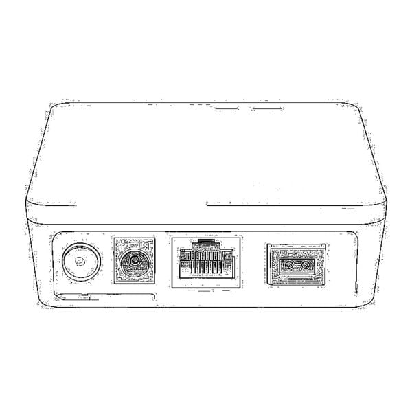 وحدة ONU GPON/EPON بسعة 1000 ميغابت/ثانية
 وحدة ONU لشبكة EPON بسرعة 10 جيجابت/ثانية/XG-PON/XGS-PON
 وحدة ONU من نوع STICK SFP بتقنية 2.5G GPON/XPON
 وحدة ONU لشبكات POE GPON/EPON
 جهاز ONT لاسلكي من نوع GPON/EPON
 EPON OLT
 وحدة OLT لشبكة GPON
 وحدة SFP PON
 المفاتيح الصناعية
 المحولات المُدارة
 محولات POE
 المحولات غير المُدارة
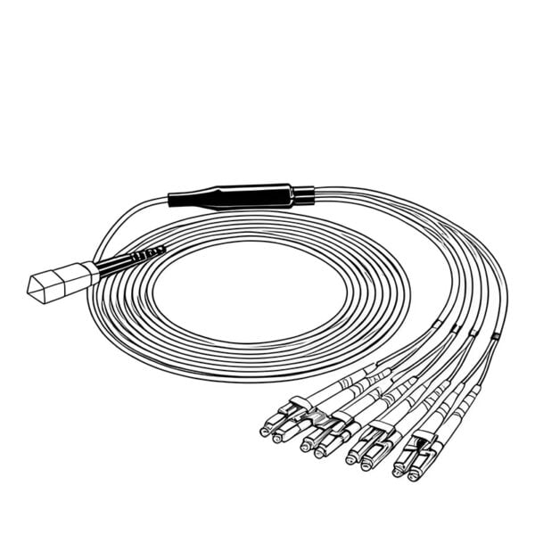 كابلات الألياف الضوئية من نوع MTP/MPO
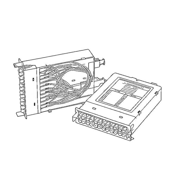 خراطيش الألياف الضوئية
 حلقة إرجاع الألياف الضوئية
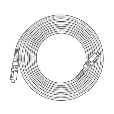 الكابلات البصرية وأطراف الألياف الضوئية
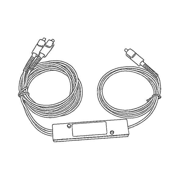 المقسمات الضوئية وصندوق المقسم
 موصلات ذات شفة ليفية
 المحولات البصرية
 مخفف ضوئي
 الموصل السريع ولوحة الموصلات
 مضخم إشارة كابل التلفزيون (CATV)
 جهاز استقبال ضوئي لشبكة الكابل التلفزيوني (CATV)
 جهاز تحديد مواقع الأعطال البصري
 OTDR
 مقياس الطاقة الضوئية
 جهاز تحديد الألياف الضوئية
 منظفات الألياف الضوئية
 مقصات الألياف ومقشرات الألياف
 الأدوات النحاسية