関税はお客様のご負担となりますが、標準ロジスティクスでは、米国、DE、英国、カリフォルニア、フランス、IT、PL、AT、JP...など、ほとんどの国へのDDPを免税でサポートしています。





















































ねんりょうプール RX LOS vs TX Fault is a directional troubleshooting question, not two names for the same failure. RX LOS means the local module is reporting a receive loss-of-signal condition. TX Fault means the local module is reporting a problem on its transmitter side.
Neither status, by itself, proves that the complete transceiver is bad. Start with the end that reports the status, map the affected direction, and then test one part of that direction at a time.
This guide covers common point-to-point optical Ethernet SFP and SFP+ links. Exact labels, polarity and status exposure can vary by module and host, so use the manuals for the actual hardware.

SFP RX LOS vs TX Fault: The One-Minute Difference
Assume a simple duplex link between device A and device B.
| Status shown at device B | What the module is reporting | First direction to examine | それが証明していないこと |
|---|---|---|---|
| RX LOS asserted | B’s receiver does not detect an acceptable incoming signal | A transmitter → A-to-B fiber path → B receiver | B’s receiver is definitely defective |
| TX Fault asserted | B’s module reports a local transmitter fault | B host power/control → B module transmitter | The B-to-A fiber is broken |
| Both asserted | B has a local TX fault and is also missing acceptable receive signal | Treat the directions separately, then check shared power, configuration and module state | One fiber cut explains every symptom |
| Neither asserted, but link is down | These two status signals do not identify the cause | PMD, rate, FEC, host mode, coding, polarity and peer state | The physical and electrical setup is compatible |
現在の SNIA SFF-8419 仕様 maps Tx_Fault as the module transmitter-fault output and Rx_LOS as the receiver loss-of-signal indication. In Ethernet, the receive signal may also be presented as Signal Detect. A host can therefore display the same underlying condition with positive or negative wording, such as RX LOS: Yes または Signal Detect: No.
Do not interpret an unfamiliar RX Fault label until the platform manual says whether it means RX LOS, low RX power, a PCS fault, or a different aggregate condition.
RX LOS Points Back Toward the Incoming Direction
If device B asserts RX LOS, begin with the optical direction that should enter B:
A TX → A connector → fiber path → B connector → B RX
Possible causes include a disabled or failed transmitter at A, crossed duplex polarity, a disconnected or contaminated connector, excessive path loss, the wrong fiber type, incompatible wavelengths or PMDs, an incorrect BiDi A/B pair, or a problem at B’s receiver. RX LOS narrows the direction; it does not select one failed component.
Check the opposite direction separately. B may receive nothing from A while A still receives normally from B. A single Link Down icon often hides that directional difference.
For a duplex link, verify that each transmitter reaches the opposite receiver. For single-fiber BiDi, verify complementary transmit and receive wavelengths; two same-direction modules are not a normal pair.
TX Fault Is Local to the Transmitter Side
If device B asserts TX Fault, concentrate first on B’s module and the way its host powers and controls the transmitter. Check whether the host intentionally asserted TX Disable, whether diagnostic data is valid after initialization, and whether voltage, temperature or another transmitter warning is abnormal for that exact module.
TX Disable and TX Fault are different signals. TX Disable is a host-to-module control that turns the transmitter off. TX Fault is a module-to-host status. A disabled transmitter can make the far end report RX LOS without proving that the transmitter has failed.
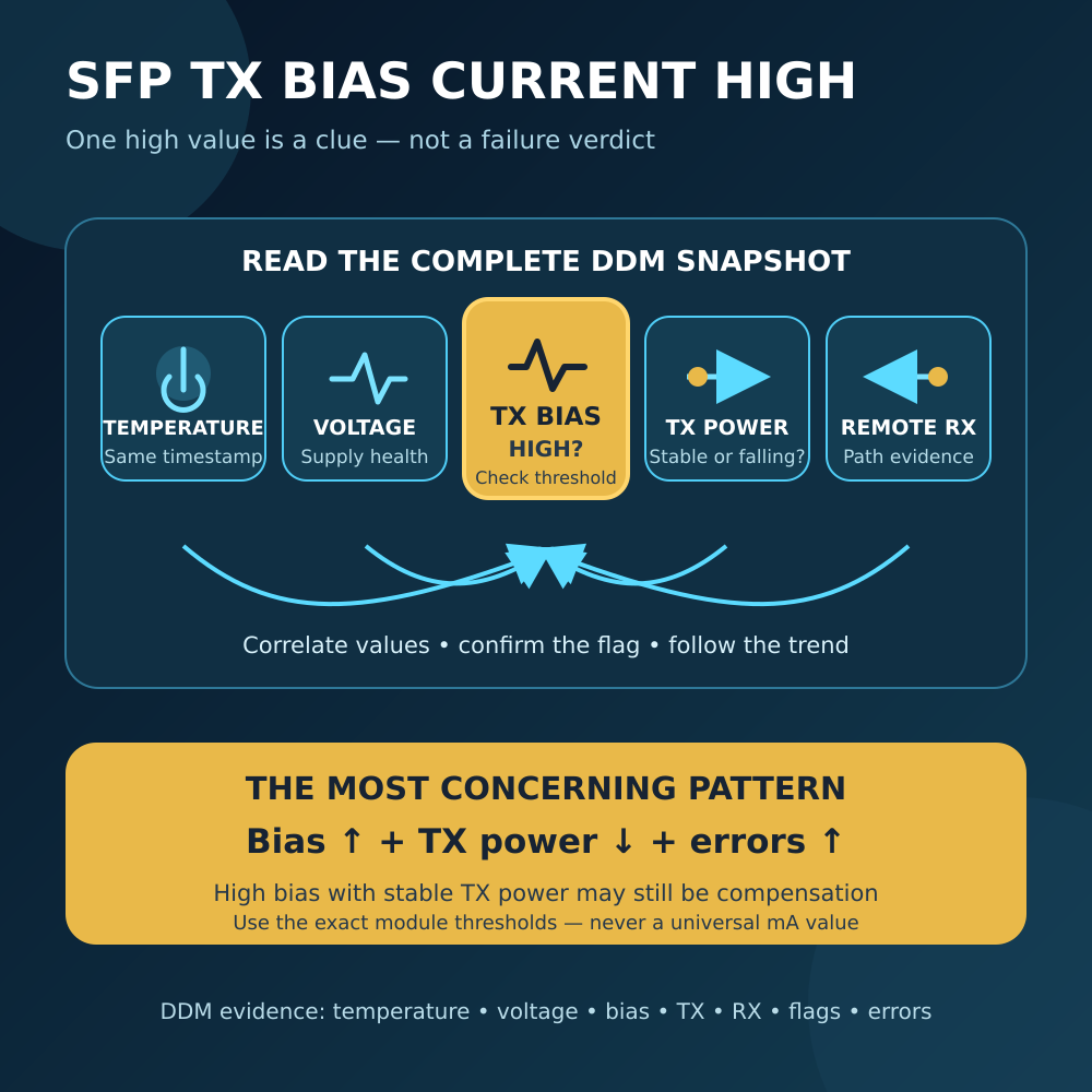
Where DDM is available, compare TX Fault with temperature, supply voltage, TX bias and TX output power from the same timestamp. LuLeey’s SFP TX bias current guide explains why a bias warning, falling TX power and TX Fault together are more informative than one isolated value.
Do not repeatedly reset or hot-plug a production module just to clear the flag. Follow the host and module procedure, preserve the original evidence, and use an approved maintenance window.
RX LOS Is Not the Same as an RX Power Alarm
SFF-8472 Rev 12.5a defines the digital TX Fault and RX LOS states separately from optional alarm and warning flags for temperature, voltage, TX bias, TX power and received optical power. It also makes soft monitoring optional.
That distinction matters:
RX LOSis a signal-state indication.RX 電力低下警告compares a monitored value with a programmed warning threshold.RX Power Low Alarmis a more serious threshold flag.- A displayed dBm value is a sampled diagnostic reading with module-specific accuracy and reporting method.
The thresholds and behavior need not be identical. A module may report some received power while still not recognizing an acceptable signal for the selected PMD and rate. Conversely, a host may not expose soft RX LOS even when it uses the physical status pin internally.
LuLeey’sを使って DDM/DOM フィールドガイド to collect the complete snapshot. Compare local TX power with remote RX power for the same direction, and use the exact module’s minimum and maximum operating limits. There is no universal “good” dBm value.
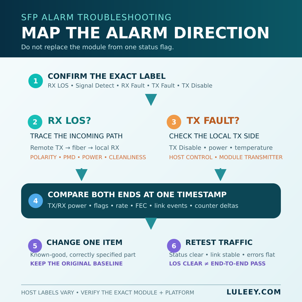
A Controlled RX LOS and TX Fault Workflow
1. Record the exact setup
Save both host models and ports, firmware and driver versions, module part numbers and revisions, coding, optical PMD, configured or negotiated rate, FEC and port mode. Record both ends’ status, DDM values, link events and error counters at the same time.
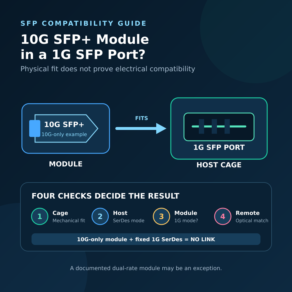
An SFP, SFP+ or SFP28 label is not a compatibility result. Physical fit, host SerDes mode, module coding, actual operating rate and usable throughput are separate facts.
2. Confirm the label and state
Read the exact platform definition for RX LOS, Signal Detect, RX Fault, TX Fault そして TX Disable. Wait until the module reports valid data after startup, then confirm a persistent status with a second reading.
Do not assume that 1 always means healthy or that a green dashboard icon overrides the raw state.
3. Map both directions
Write the link as two paths:
- A TX → B RX
- B TX → A RX
If B has RX LOS, check the first path. If B has TX Fault and A has RX LOS, the two observations agree on the B TX → A RX direction and make B’s transmit side a stronger candidate. They still do not rule out host power, TX Disable or a second fault.
4. Verify the optical match
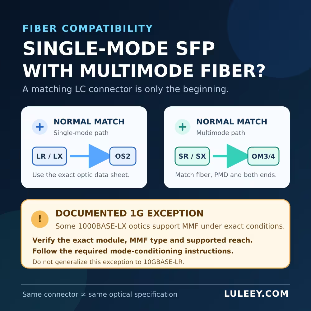
Confirm rate and PMD, fiber category, wavelength, connector family and polish, duplex polarity or BiDi pairing, and the receive-power window in each direction. A connector that fits is not enough.
Inspect and clean accessible connectors using the network owner’s approved procedure. The 光ファイバー協会 コネクタガイド documents how contamination causes loss and reflectance and can transfer between mated ferrules. Never look into a fiber or optical port; use a suitable power meter and video inspection method.
5. Isolate one component
During an approved maintenance window, substitute one known-good, correctly specified patch lead or module and repeat the same observations. If the fault follows one module between supported ports, that strengthens the module hypothesis. If RX LOS stays with one fiber direction, inspect that path. If it stays with one host port, investigate the host and configuration.
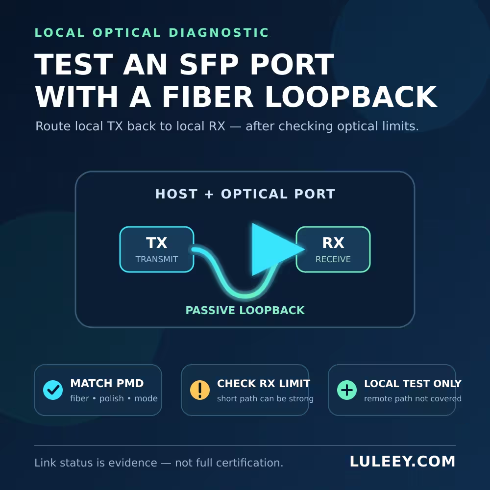
A local loopback can narrow the local path, but only after matching the PMD, fiber, connector and receiver power. LuLeey’s fiber-loopback test guide explains the limits: a successful loop does not test the production trunk or remote peer, and a passive self-loop is not a valid general test for complementary-wavelength BiDi optics.
6. Validate traffic, not only status
After the status clears, verify stable link state, actual rate and new counter deltas in both directions. RX LOS being clear only says that this particular loss indication is not asserted. It does not prove clean Ethernet frames or expected throughput.
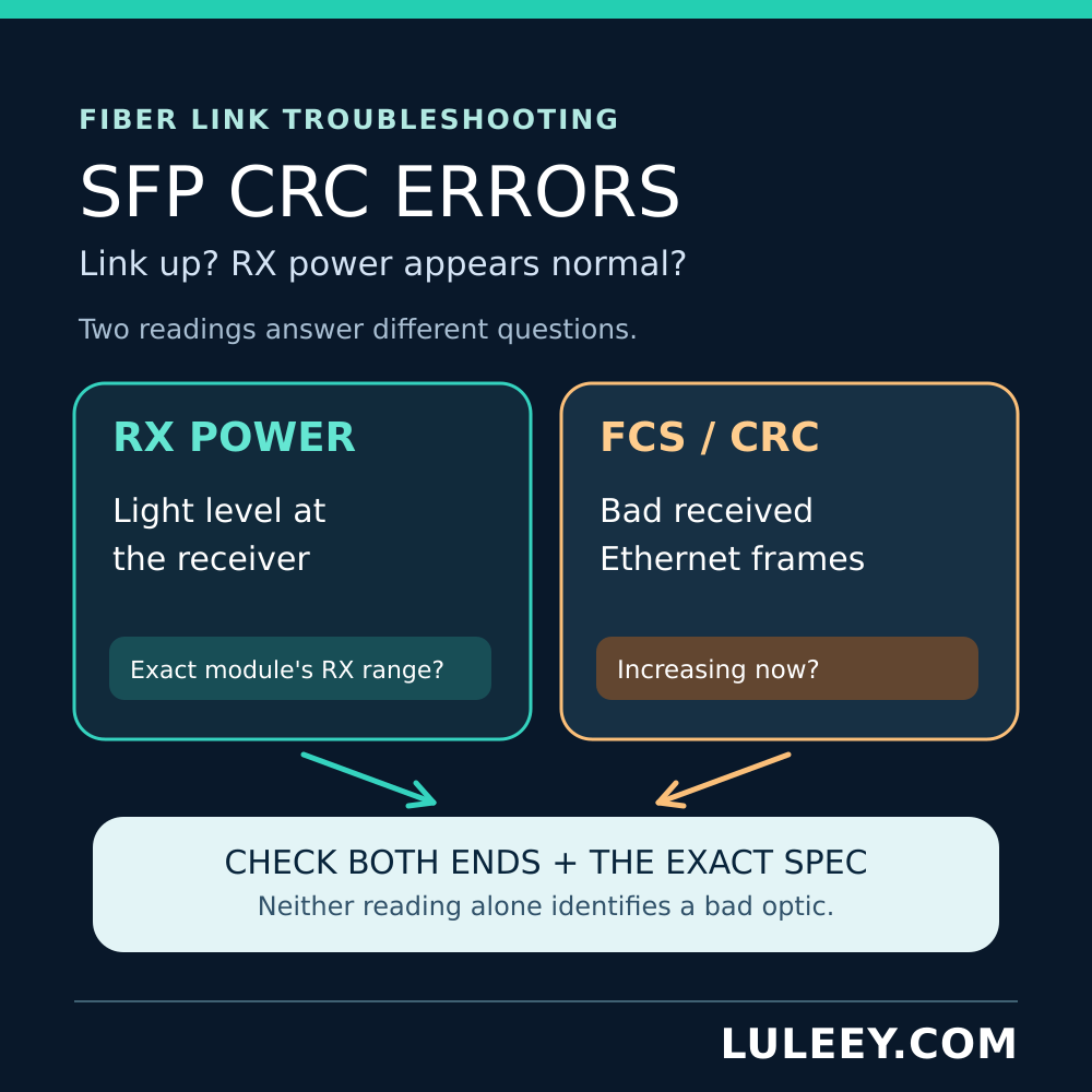
If the link is up but FCS/CRC errors increase, continue with LuLeey’s SFP CRC troubleshooting checklist.
避けるべきよくある間違い
- Replacing B’s receiver merely because B reports RX LOS
- Treating TX Disable as proof of TX failure
- Reading local TX and local RX values as one optical direction
- Swapping both optics and both patch leads at once
- Using a generic wavelength or dBm rule instead of the exact data sheets
- Declaring success when the alarm clears without checking traffic and counters
- Ignoring host SerDes, rate, FEC, coding, firmware or port settings
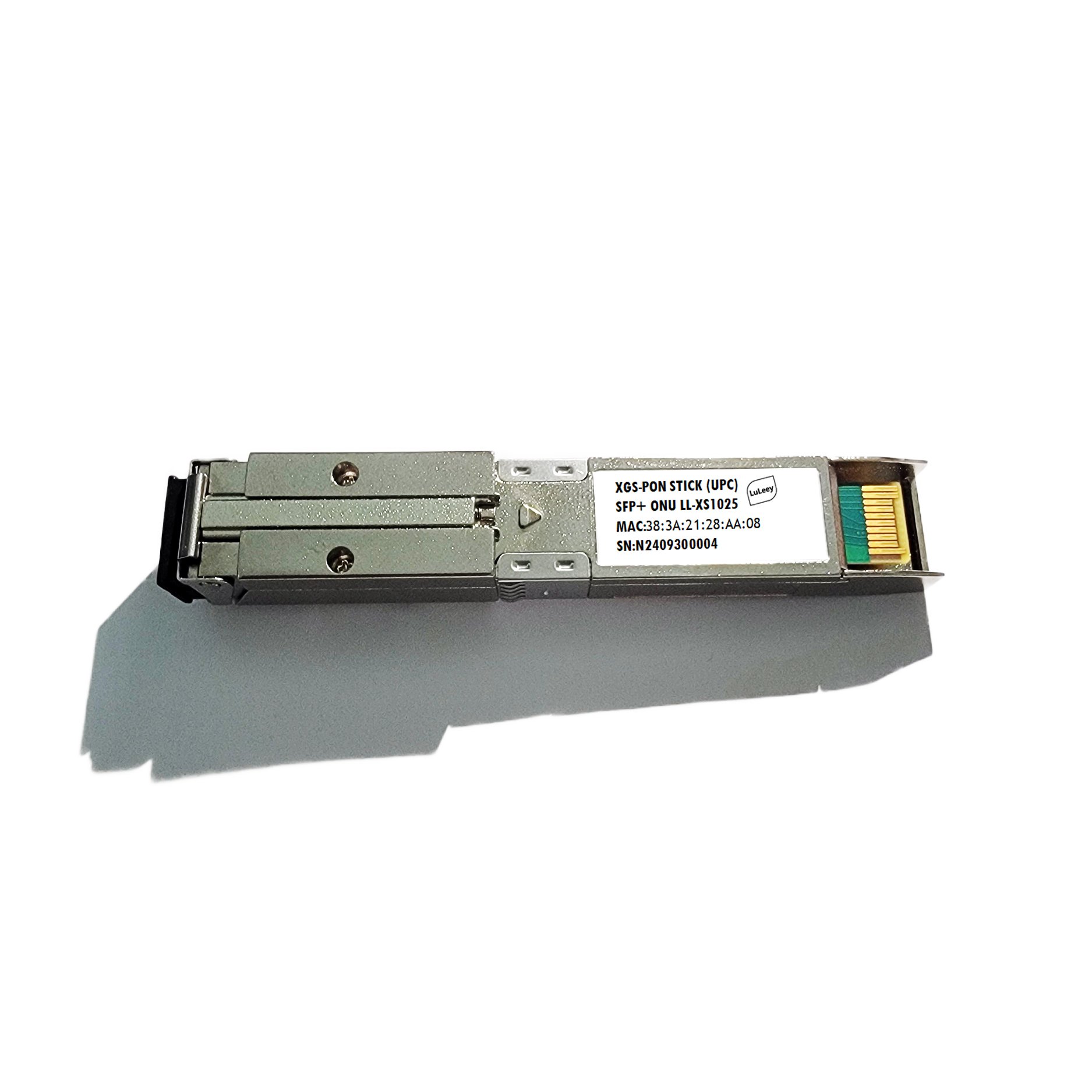
This workflow is not a PON registration guide. A 2.5G PON ONU Stick contains ONU logic and may expose host behavior differently. A 1G/10G SFP+ host can carry it at 1G only when both the Stick and host support a compatible 1G mode; some SFP+ ports can support 2.5G only with the right chipset/PHY, firmware or driver, port settings, module coding and Stick host mode.
LuLeey Equipmentの活用シーン
For a controlled local multimode test, LuLeey’s LC/UPC OM3 fiber loopback page lists a 50/125 µm multimode path, LC/UPC interface and insertion loss of no more than 0.2 dB. Those specifications do not make it universal. The value is a maximum loss, not guaranteed protective attenuation; verify the exact PMD and receiver maximum input before making a short loop.
For a replacement or compatibility check, send LuLeey both host models, module labels and revisions, firmware, port mode, fiber and connector details, both ends’ TX Fault/RX LOS/TX Disable states, full DDM snapshots, link-event timestamps and counter deltas.
 SFP/SFP+ (1G/2.5G/5G/10G)
 SFP-T (1G/2.5G/10G)
 AOCケーブル 10G/25G/40G/100G
 DACケーブル 10G/25G/40G/100G
 qsfp28 qsfp+ sfp28 100g/40g/25g
 銅線-光ファイバー・メディア・コンバーター
 ファイバーメディアコンバータPCBAボード
 OEOファイバー・メディア・コンバーター
 シリアル-ファイバー・メディア・コンバーター
 ビデオ-ファイバー・メディア・コンバーター
 1000m Gポン/エポン・オヌ
 10Gエポン・オヌ/XG-PON/XGS-PON
 2.5g Gpon/XponスティックSFP ONU
 ポー・グポン/エポン・オヌ
 ワイヤレスGPON/EPON ONT
 エポンOLT
 GPON OLT
 SFP PONモジュール
 産業用スイッチ
 マネージド・スイッチ
 POEスイッチ
 アンマネージド・スイッチ
 MTP/MPOファイバーケーブル
 光ファイバーカセット
 光ファイバーループバック
 光ケーブルとファイバーピグテール
 光スプリッターとスプリッターボックス
 ファイバーフランジコネクター
 光アダプター
 光減衰器
光減衰器 クイックコネクターとコネクターパネル
 CATVアンプ
 CATV光受信機
 ビジュアル・フォルト・ロケーター
 OTDR
OTDR 光パワーメーター
 光ファイバー識別器
 光ファイバー・クリーナー
 ファイバー・クリーバー&ファイバー・ストリッパー
 銅工具
銅工具


