関税はお客様のご負担となりますが、標準ロジスティクスでは、米国、DE、英国、カリフォルニア、フランス、IT、PL、AT、JP...など、ほとんどの国へのDDPを免税でサポートしています。





















































もしあなたの ファイバーはaを通過し、 VFLテスト しかし、まだリンクがありません, 、そのケーブルが必ずしもデータ伝送に適しているとは限りません。反対側で赤色光が確認できることは、主に連続した光路が存在することを示すに過ぎません。これは、リンク損失、コネクタの品質、波長、偏光、プロトコル、トランシーバーの速度、あるいは受信電力が適切であることを証明するものではありません。.
A ビジュアル・フォルト・ロケーター ジャンパー線の断線箇所を見つけたり、光ファイバーの経路を追跡したり、基本的な導通を確認したり、急な曲がりやひび割れのある箇所を特定したりするのに役立ちます。ただし、これは完全な光ファイバー認証ツールではありません。.
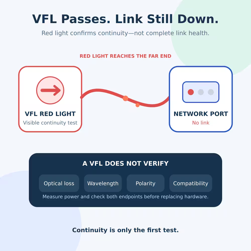
VFLテストの成功が実際に何を証明するのか
VFLは、可視赤色レーザー光(通常は約650nm)をファイバーに注入します。赤色光が反対側の端まで到達すれば、そのファイバーは少なくともある程度の光を一方の端からもう一方の端まで伝送できることになります。.
テストが成功すれば、以下の結論を裏付けることができます:
- その繊維は、おそらく完全に切れてはいないでしょう。.
- テスト対象の経路は、おそらく想定された遠端コネクタに到達していると考えられます。.
- 目視できるほど近い位置に、大きな断層が存在しない場合もあります。.
- このファイバーは、パッチパネルまたはバンドルをたどって追跡することができます。.
- 強い赤色の光漏れは、亀裂、激しい曲がり、不適切な機械的接続、または損傷した接続箇所の特定に役立つ場合があります。.
光ファイバー協会は、VFLを導通検査、トレース、および断線や高損失箇所の視覚的な特定を行うためのツールと説明しています。そこがVFLの強みです。.
しかし、「可視光が一部到達する」ということは、「そのリンクが光学的予算を満たしている」ということとは同じではありません。“
VFLテストでは証明できないこと
挿入損失は測定しません
目視だけでは、赤色光の明るさを信頼できるdB値に変換することはできません。損失が大きすぎるケーブルであっても、特に短いジャンパーケーブルの場合や高出力のVFLを使用している場合には、遠端で赤色光が視認できることがあります。.
損失を測定するには、校正済みの光源を使用し、 光パワーメータ 有効な基準信号を用いて。動作中の受信機の入力を確認するには、正しい波長で光パワーを測定し、受信機の正確な仕様値と比較してください。.
動作波長を検証しません
VFLは可視赤色光を使用しますが、通信システムでは通常、赤外線の波長が使用されます。650nmの光を伝送するファイバー経路であっても、システムの波長において必ずしも正常に動作するとは限りません。.
また、2つのトランシーバーが互いに一致する波長を使用しているかどうかも確認できません。U/Dの組み合わせが間違っているBiDiペアは、導通テストに合格しても、リンクが確立されない場合があります。.
Tx/Rxの極性は検証されません
VFLは個々の光ファイバーを追跡するのに役立ちますが、1本のファイバーを通して赤色光が見えるからといって、デュプレックスリンクにおいて送信機の出力が正しい受信機の入力に到達していることを証明するものではありません。.
2ファイバーのイーサネットの場合、一方の側のTX信号は、もう一方の側のRXに到達しなければなりません。リンクがダウンしている間は、両方のファイバーが連続していても、その位置が逆になっているため、問題にはなりません。.
プロトコルや速度の検証は行いません
連続ファイバーでは、互換性のない機器間の通信を実現することはできません。例としては、次のようなものがあります:
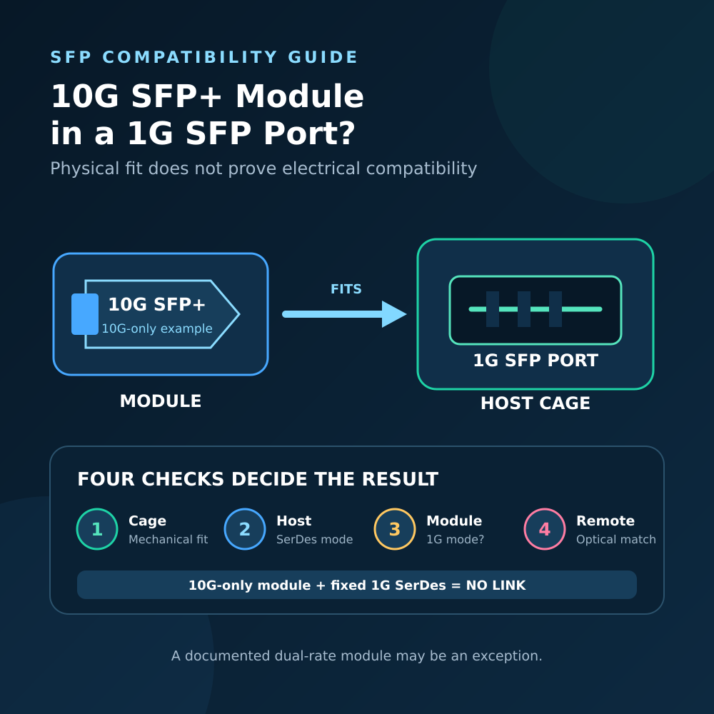
- 1G ねんりょうプール サポートされていないモードに固定されたホストポートとペアになっている
- 10Gモジュールと、1G専用のリモートモジュールを組み合わせた構成
- PONインターフェースに接続されたイーサネットトランシーバー
- 互換性のないXGS-PONサービスで使用されているGPON ONU
- コーディング、ファームウェア、ドライバ、またはホストのポリシーを理由に拒否されたモジュール
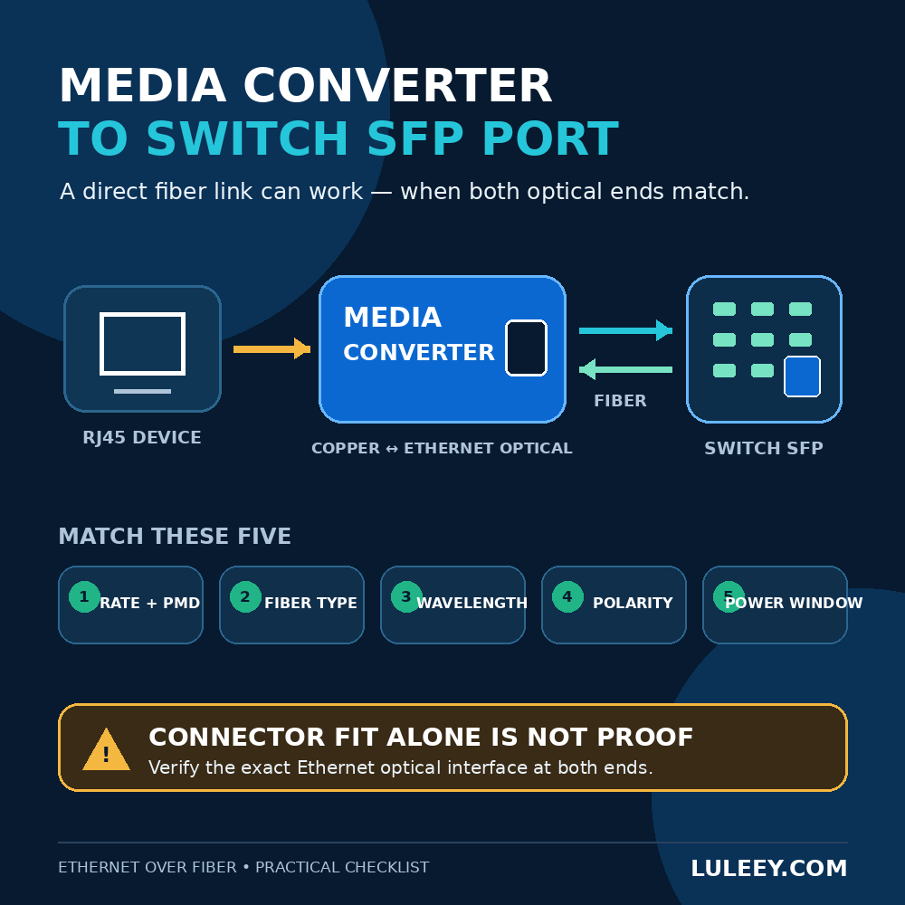
SFPまたはSFP+の物理的なケージだけでは、互換性が保証されるわけではありません。ホストのSerDesモード、設定またはネゴシエーションされた転送速度、モジュールのエンコーディング、ファームウェア、ドライバ、およびリモートエンドポイントなどを正確に確認してください。.
それだけでは、受信機の電力が安全であることを証明するものではありません
コネクタの汚れ、スプリッタの損失、ケーブルの曲がり、接続部の継ぎ目、あるいは距離が原因で、受信信号が弱すぎる可能性があります。また、信号が強すぎて、短いリンクでは感度の高い受信機に過負荷がかかる場合もあります。.
VFLでは、これらの条件を区別することはできません。.
コネクタの清浄性が証明されるわけではありません
コネクタが汚れていると、可視光は通過する一方で、サービス波長域では損失や反射が生じることがあります。また、コネクタを再接続すると、汚染物質がきれいなアダプタやトランシーバのポートに移ってしまう可能性もあります。.
リンクがまだ復旧していない7つの理由
1. コネクタの端面が汚れている、または損傷している
ほこり、油分、傷は、挿入損失や反射を増大させる原因となります。適切な手順に従って、手が届くすべての接続部を点検・清掃した後、フェルールに触れないようにして再接続してください。.
光出力が存在しないことを確認するまでは、直視型顕微鏡を使用して未知のファイバーを検査してはなりません。.
2. VFLが定量化できない過大な損失
接続部の接触不良、接続部の緩み、配線の長さ、スプリッター、あるいはいくつかの小さな損失があると、目には十分な量の可視赤色光が見える一方で、実際の受信機は感度限界を下回ってしまうことがあります。.
RX出力をdBm単位で測定するか、挿入損失試験を実施してください。その結果を、一般的な「適切なファイバー出力」値ではなく、当該のトランシーバー、ONU、またはONTの正確な仕様値と比較してください。.
3. デュプレックス送受信の極性が逆になっている
これは2芯のリンクに適用されます。現在の位置にラベルを付け、一方の端のみの2本の光ファイバーを入れ替えてから、リンクを再度確認してください。リンクが依然としてダウンしている場合は、元の配置に戻してください。.
この方法は、単一ファイバーのBiDi、PON、AOC、またはMPO接続には適用しないでください。LuLeeyの ファイバーの送受信極性ガイド 正しい適用範囲と手順について説明しています。.
4. 波長の不一致またはBiDiペアリング
通常のデュプレックス・トランシーバー2台は、通常、両端で同じ動作波長を使用します。一方、シングルファイバーBiDiモジュールでは、送信波長と受信波長が互いに補完し合う必要があります。.
通常、送信波長が同じ2つのモジュールは、互いに通信することができません。「10G」や「20km」、あるいはコネクタの種類だけに頼るのではなく、完全な型番とTX/RX波長表を確認してください。.
5. ファイバーの種類が光学部品と一致しない
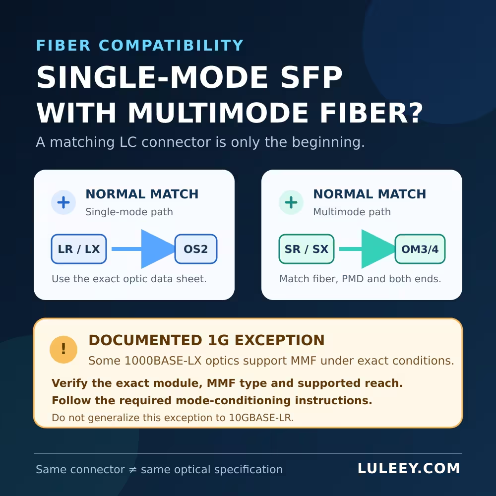
シングルモード光ファイバーかマルチモード光ファイバーか、コネクタの研磨状態、コアの種類、およびトランシーバーの仕様を確認してください。光学系が適合していなくても、コネクタは機械的には接続できる場合があります。.
6. モジュール、ポート、またはホストモードが互換性がない
両方のエンドポイントを確認してください:
- スイッチ、ルーター、NIC、メディアコンバーター、ONU、またはONTの正確な型番
- ポート速度および対応するSerDesモード
- オートネゴシエーションまたは強制速度設定
- モジュールのコーディングとベンダーポリシー
- ファームウェアおよびドライバのバージョン
- モジュールの電力および熱に関する制限
- アラーム、LOS、および診断ログ
モジュールがケージに収まるという理由だけで、あるいはその名称に「SFP」、「SFP+」、または公称データレートが含まれているという理由だけで、そのモジュールが互換性があるとは結論づけてはなりません。.
7. 光路は機能しているが、サービスが提供されていない
これはPONネットワークではよくあることです。ONUはダウンストリーム光信号を受信していても、シリアル番号、LOID、パスワード、OMCIプロファイル、VLAN、サービスプロファイル、OLT認証が正しくない場合や、サポートされていないONUとOLTの組み合わせである場合などにより、登録に失敗することがあります。.
VFLの継続性テストでは、登録やサービス設定を検証することはできません。.
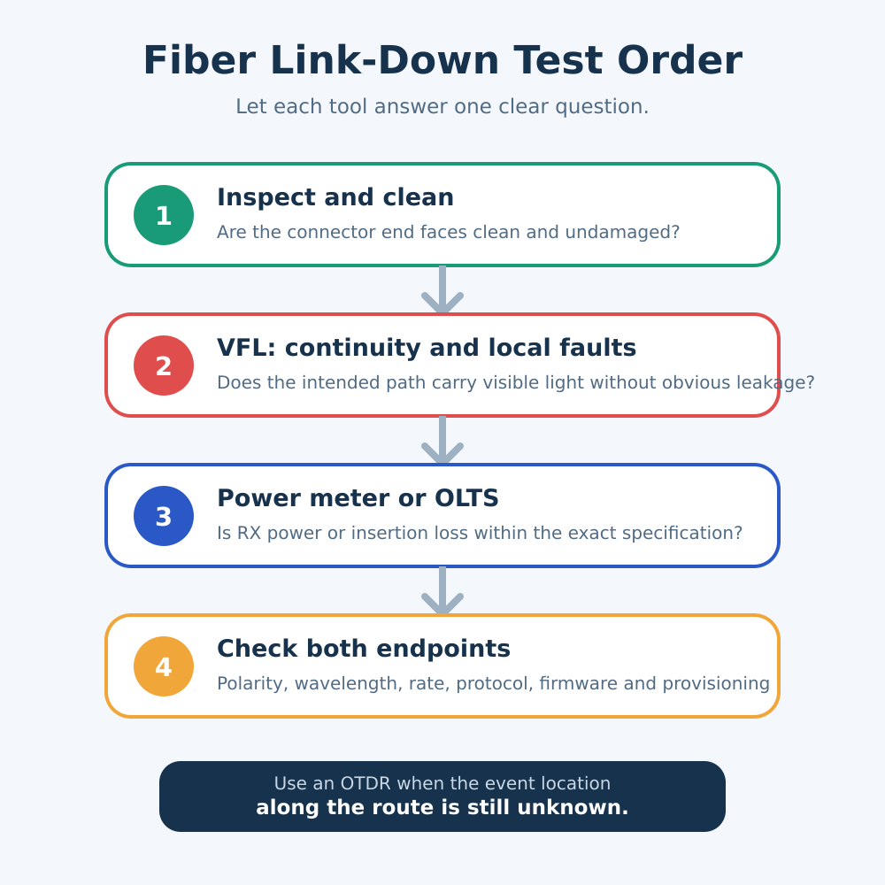
より効果的なトラブルシューティングの手順
手順 1:繊維を安全に扱える状態にする
ネットワーク事業者および機器の取り扱い手順に従ってください。必要に応じて、稼働中の機器の接続を解除してください。不明な光ファイバーを取り扱う、または点検する前に、パワーメーターを使用して光パワーを確認してください。.
ファイバーコネクタ、トランシーバー、アダプタ、またはVFLの出力部を絶対に覗き込まないでください。VFLの漏れ光は、ファイバーの軸方向ではなく、横から確認してください。.
ステップ2:点検と清掃
ファイバーが安全であることを確認した後、アクセス可能な端面を点検してください。目視で損傷が確認されたジャンパーは、清掃し、再点検した上で交換してください。.
ステップ3:VFLを使用して導通および局所的な故障を検査する
適切なアダプターを接続し、必要に応じて連続モードまたはパルスモードを選択して、ファイバーをトレーシングします。曲がり部分、コネクタ、スプライス、または損傷箇所で光漏れがないか、横から確認してください。.
作業に適した出力レベルのみを使用し、装置のレーザー分類および安全上の指示に従ってください。表示されているmW値が大きいからといって、その試験がより優れている、あるいはより正確であるという証拠にはなりません。.
LuLeey’s 650nm可視光式故障位置特定装置 トレースや目視による故障箇所の特定のために、連続動作およびパルス動作に対応しています。公称距離だけで選ぶのではなく、実際の使用環境に合わせてバージョンとコネクタアダプタを選択してください。.
手順 4:トポロジーと極性を確認する
対象のファイバーをテストしたことを確認してください。デュプレックス接続の場合は、両方のストランドを追跡し、TXからRXへのルーティングを確認してください。BiDiおよびPONの場合は、その接続が1本のファイバーを使用する仕様であることを確認してください。.
ステップ5:光パワーまたは光損失を測定する
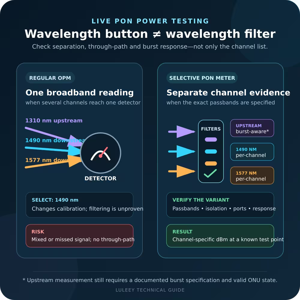
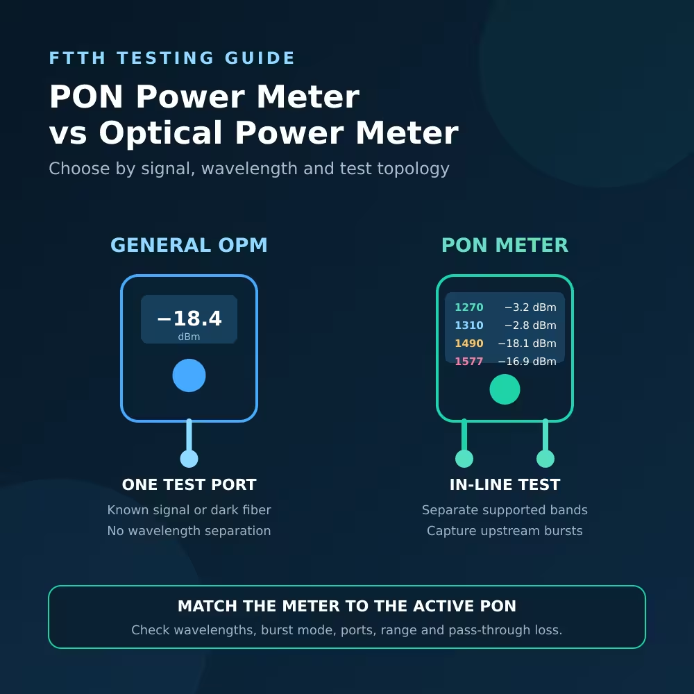
動作波長および想定される出力範囲に対応した光パワーメーターを使用してください。適切な波長設定を選択してください。.
正式な挿入損失試験を行う際は、互換性のある試験用信号源、基準ケーブル、および適切に確立された基準を使用してください。誤った波長で、あるいは正しい基準を使用せずにパワーメーターで測定した値は、誤解を招く恐れがあります。.
LuLeey’s 光パワーメータのカテゴリ 一般的なパワーメーターやPON専用テスターなどが含まれます。波長、測定範囲、コネクタ、および測定対象が切断されたファイバーか、稼働中のPONかによって、適切な機種をお選びください。.
手順 6:機器の正確な仕様と照合する
両端点の送信電力、受信電力、受信感度、過負荷限界、波長、伝送速度、距離クラス、ファイバーの種類、およびコネクタの研磨状態を記録する。.
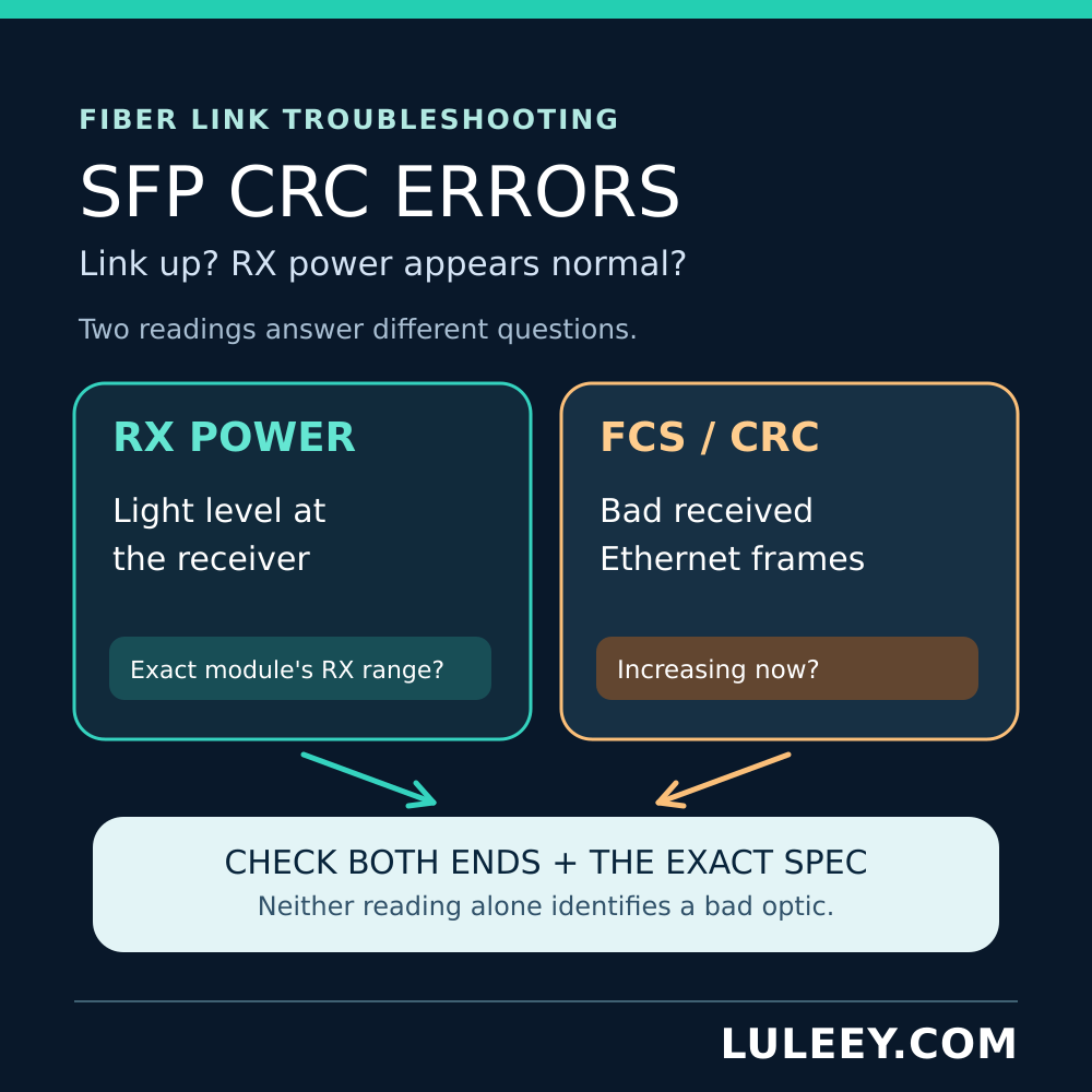
DDM/DOMの測定値は参考になりますが、実装上の制約や精度の限界があります。測定結果が閾値に近い場合は、適切な校正済みの試験装置を用いて確認してください。.
手順 7:機器およびサービスの設定を確認する
ポートの状態、速度、ファームウェア、ドライバ、モジュールのアラームおよびエラーカウンタを確認してください。PONについては、光パワーが許容範囲内であることを確認した後、登録およびOLTのプロビジョニングを確認してください。.
OTDRをいつ使用すべきか
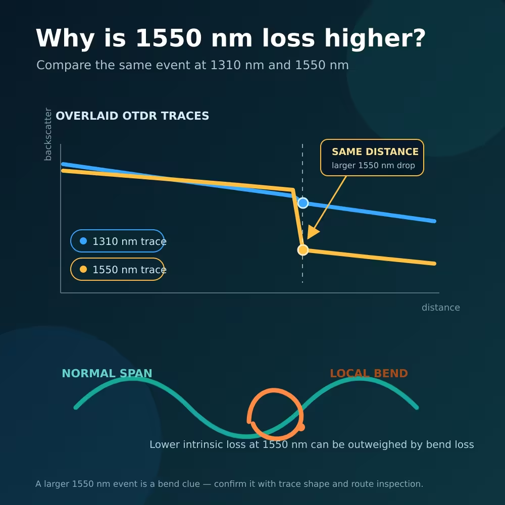
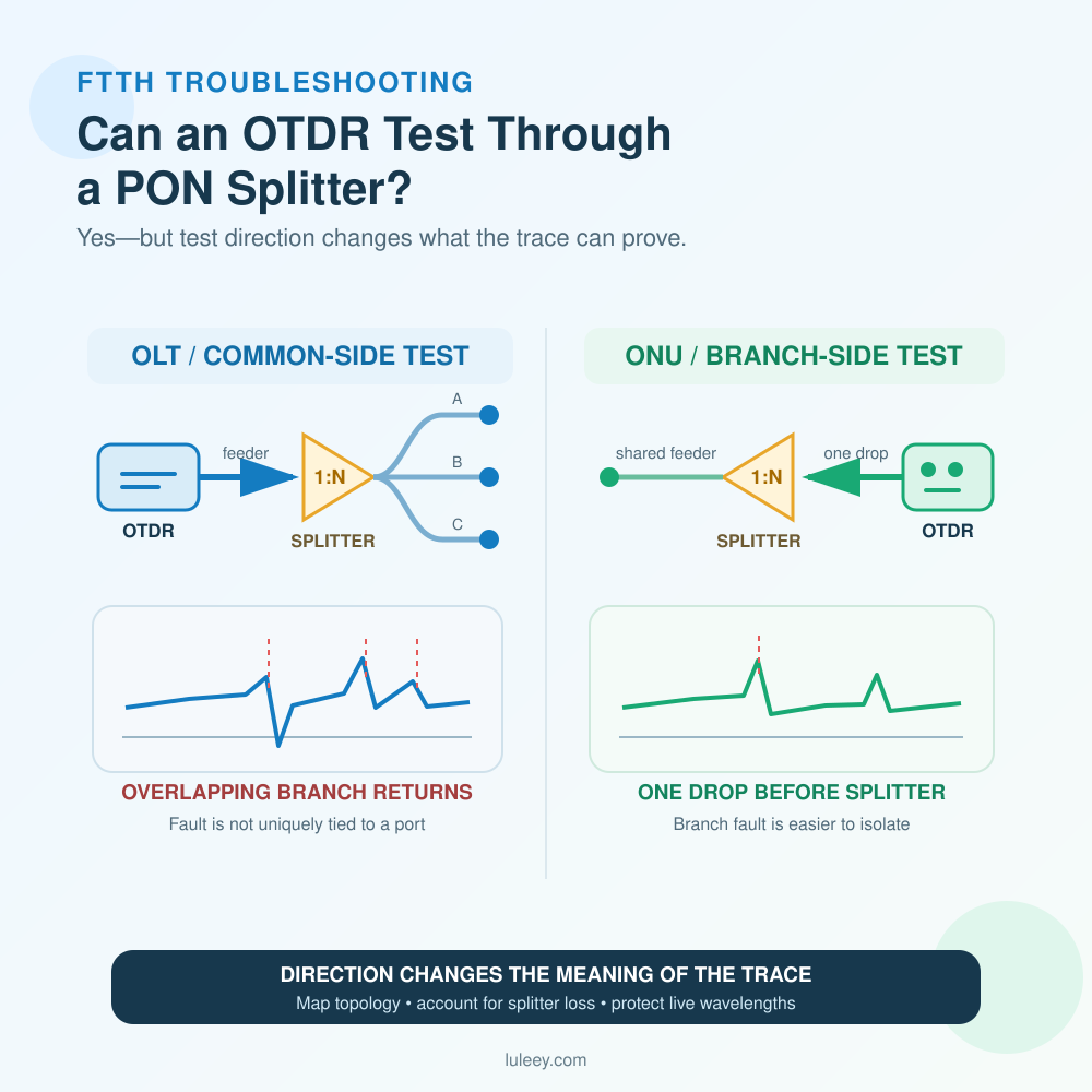
断線、反射型コネクタ、不適切なスプライス、予期せぬ損失箇所など、長距離の回線やアクセスが困難な回線上の異常箇所を特定する必要がある場合は、OTDRを使用してください。.
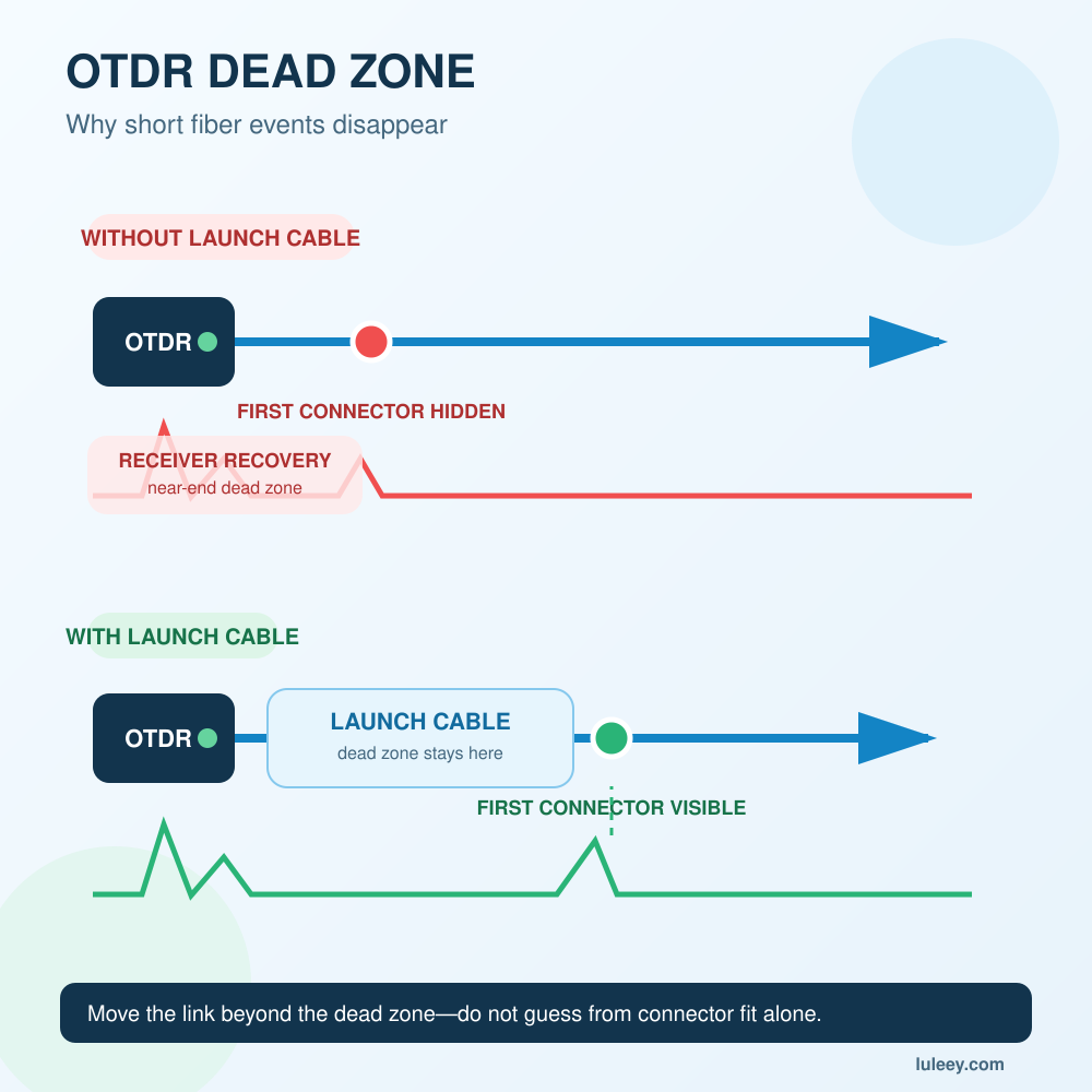
OTDRを使用するには、適切な波長、パルス幅、測定範囲、屈折率の設定、送信ケーブル、そして多くの場合、受信ケーブルも必要です。そのトレースは、デッドゾーン、イベント損失、反射率、および後方散乱について理解している者が解釈する必要があります。.
OTDRは、エンドツーエンドの挿入損失試験の代わりにはなりません。光ファイバー協会(Fiber Optic Association)は、光源とパワーメーターを用いた試験ではケーブル設備の損失を直接測定するのに対し、OTDRは後方散乱から間接的に測定を行うと指摘しています。.
最終的な答え
赤いVFLの光がリンクの反対側まで届いているにもかかわらず、ファイバーリンクがダウンしたままである場合、VFLが明らかにしているのは以下の1点のみです:
その道には、わずかな光が差し込んでいる。.
次に、清浄度、測定された光パワーまたは光損失、デュプレックス極性、波長ペア、ファイバーの種類、モジュールの互換性、ホストポートのモード、およびサービスのプロビジョニングを確認してください。.
以下の順序でツールを使用してください:
- 点検と清掃
- VFL:連続性および目視可能な局所的な欠陥の検出
- 出力および損失の測定用光パワーメーターまたはOLTS
- DDM、ログ、および互換性に関するデバイス仕様
- 事象の発生場所が不明な場合のOTDR
テスターを選定する前に、LuLeeyに対し、ネットワークの種類、波長、コネクタ、想定される出力範囲、経路の長さ、および光ファイバーを稼働させたまま測定できるかどうかを伝えてください。これらの詳細情報に基づいて、その作業にVFL、標準パワーメーター、波長選択型PONメーター、あるいはOTDRのどれが必要かが決まります。.

 SFP/SFP+ (1G/2.5G/5G/10G)
 SFP-T (1G/2.5G/10G)
 AOCケーブル 10G/25G/40G/100G
 DACケーブル 10G/25G/40G/100G
 qsfp28 qsfp+ sfp28 100g/40g/25g
 銅線-光ファイバー・メディア・コンバーター
 ファイバーメディアコンバータPCBAボード
 OEOファイバー・メディア・コンバーター
 シリアル-ファイバー・メディア・コンバーター
 ビデオ-ファイバー・メディア・コンバーター
 1000m Gポン/エポン・オヌ
 10Gエポン・オヌ/XG-PON/XGS-PON
 2.5g Gpon/XponスティックSFP ONU
 ポー・グポン/エポン・オヌ
 ワイヤレスGPON/EPON ONT
 エポンOLT
 GPON OLT
 SFP PONモジュール
 産業用スイッチ
 マネージド・スイッチ
 POEスイッチ
 アンマネージド・スイッチ
 MTP/MPOファイバーケーブル
 光ファイバーカセット
 光ファイバーループバック
 光ケーブルとファイバーピグテール
 光スプリッターとスプリッターボックス
 ファイバーフランジコネクター
 光アダプター
 光減衰器
光減衰器 クイックコネクターとコネクターパネル
 CATVアンプ
 CATV光受信機
 ビジュアル・フォルト・ロケーター
 OTDR
OTDR 光パワーメーター
 光ファイバー識別器
 光ファイバー・クリーナー
 ファイバー・クリーバー&ファイバー・ストリッパー
 銅工具
銅工具


