関税はお客様のご負担となりますが、標準ロジスティクスでは、米国、DE、英国、カリフォルニア、フランス、IT、PL、AT、JP...など、ほとんどの国へのDDPを免税でサポートしています。



光リターンロス vs 反射率 同じ反射光が正負逆の符号で表現されることがあるため、混乱を招く。ある OTDR 表示される場合がある -50 dB あるコネクタの反射率と 45 dB ORL リンク全体については、どちらの値も自動的に間違っているわけではありません。.
重要なのは測定範囲です。反射率は通常、1回の測定結果を表し、一般的には負のdB値で示されます。光反射損失(ORL)は通常、コンポーネントやリンクから反射されるすべての光を表し、一般的には正のdB値で示されます。反射率は負の値が大きいほど良く、ORLは値が大きいほど良いとされます。.
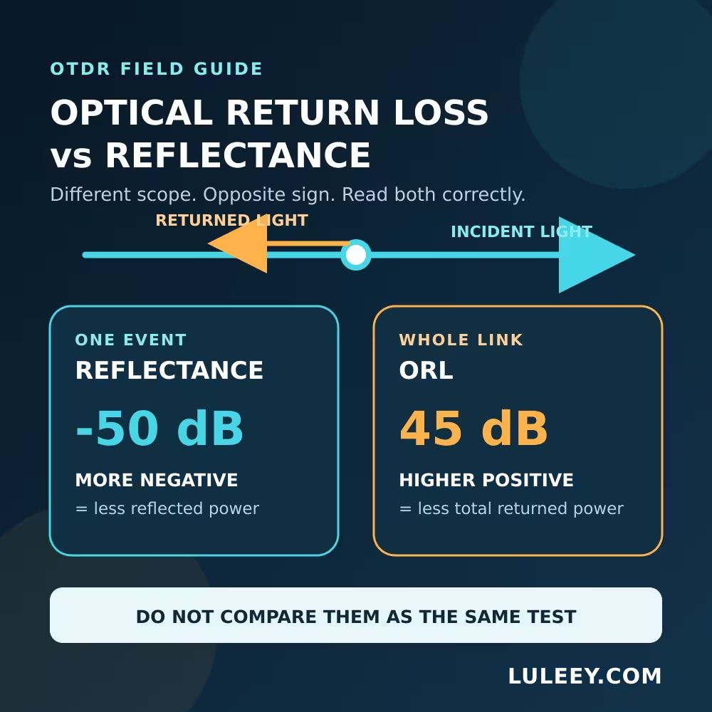
光リターンロスと反射率の関係:簡単な答え
| 読書 | その内容 | 一般的な式 | より良い結果 |
|---|---|---|---|
| イベント反射率 | コネクタ、機械的接続部、開放端、またはその他の反射現象から返ってきた電力 | 10 × log10(Pr / Pi) | さらに否定的なものとしては、例えば -60 dB ~の代わりに -40 dB |
| コンポーネントの反射損失 | その構成要素が反映する総出力に対するインシデント出力 | 10 × log10(π / Pr) | より高い正の値、例えば 60 dB ~の代わりに 40 dB |
| 全リンクORL | すべての反射事象からの総反射電力と、分散後方散乱の合計 | 10 × log10(Plaunch / Preturned,total) | 同じ試験方法において、より高い正の値が得られた |
π 入射光パワーであり、 Pr は反射光パワーである。. IEC 61300-3-6 リターンロスとは、入射電力と総反射電力の比として定義される。.
測定器によっては、個々のイベントに対して「リターンロス」を用いるものもあれば、「反射率」を用いるものもあります。ラベルの表記だけを鵜呑みにしないでください。符号、測定範囲、および測定器の取扱説明書を確認してください。.
「反射率」とは何か?
反射率は、ある不連続部からどれだけの光パワーが反射して戻ってくるかを示します。コネクタの端面、空気隙間、機械的スプライス、あるいは開放されたファイバー端面は、フレネル反射を引き起こす可能性があります。一方、融着スプライスや滑らかな曲げ部は、通常、主に非反射性の損失として現れます。.
反射率(dB)= 10 log10(Pr / Pi)
反射電力は入射電力よりも小さいため、結果は通常、負の値となります。.
-40 dBを表す0.01%反射電力。.-50 dBを表す0.001%.-60 dBの10分の1の電力を返す-50 dB.
したがって、, -60 dB 反射率は~よりも優れている -40 dB.
光リターンロスとは何ですか?
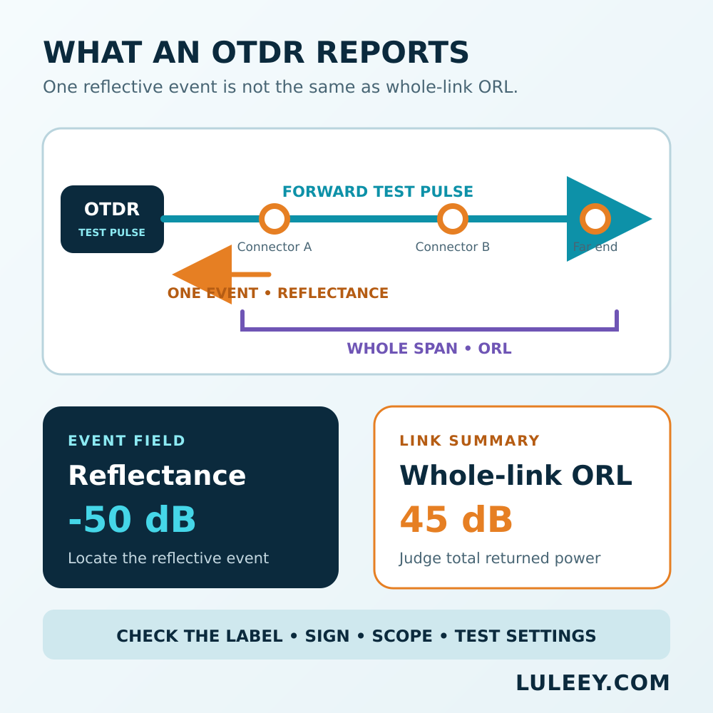
反射損失は、この比率を逆転させます:
反射損失(dB)= 10 log10(Pi / Pr)
For one isolated event, -50 dB reflectance corresponds numerically to 50 dB return loss.
Whole-link ORL is broader. It combines returned power from every reflective event and the fiber’s distributed Rayleigh backscatter. It is not simply the sign-flipped reflectance of the worst connector. The Fiber Optic Association’s guide explicitly distinguishes event reflectance from link ORL.
For a simplified example, two identical -50 dB reflections, ignoring propagation loss and backscatter, combine to approximately -47 dB aggregate reflectance or 47 dB return loss. A real link also includes two-way attenuation, backscatter and additional events, so use the measured result rather than this shortcut.
Why OTDR Labels Can Be Misleading
Terminology is not perfectly consistent across instrument menus and reports.
- One report may show
Reflectance -52 dB. - Another may show
Return Loss 52 dBfor the same type of event. - A summary labeled
ORL 35 dBmay cover the complete trace. - Some software calculates ORL only between selected markers.
Before comparing values, confirm:
- Is the result for one event, one component or the full span?
- Is the ratio
Pr/PiまたはPi/Pr? - Is it negative reflectance or positive return loss?
- Were wavelength, pulse width, range and marker boundaries identical?
How to Read Reflectance and ORL on an OTDR
1. Make the fiber safe to test
Treat an unknown fiber as live. Follow the network owner’s procedure, verify its status with an approved detector or power meter, and never use a direct-view microscope on a potentially active connector.
Do not connect a standard OTDR to an active PON unless the exact wavelength, filtering and in-service method are approved.
2. Inspect and clean every interface
Inspect, clean and re-inspect the OTDR port, test cords and link connectors. Contamination can add both insertion loss and reflection.
Match the fiber type and connector polish. Do not mate APC and UPC connectors.
3. Use launch and receive fibers
A launch fiber moves the first connector beyond the near-end dead zone. A receive fiber supplies backscatter after the final connector so that event can be evaluated.
LuLeey’s OTDRのデッドゾーンに関するガイド explains why the required length depends on the actual pulse and range settings.
4. Start with the shortest practical pulse
A shorter pulse improves event separation. A wider pulse provides more dynamic range but increases the dead zone and may saturate the receiver after a strong reflection.
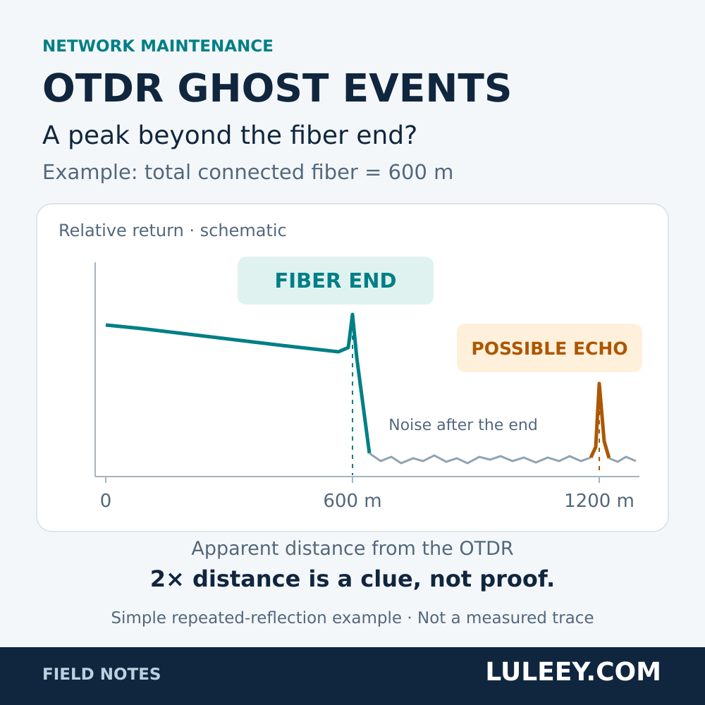
A flat-topped reflection peak indicates possible saturation. In that condition, the displayed reflectance is unreliable. OTDR reflectance is indirectly estimated from backscatter, pulse-width correction and the reflected peak.
5. Separate three results
Read these independently:
- Event loss: change in backscatter across an event.
- Event reflectance or event return loss: returned power from that event.
- Whole-link ORL: total returned power within the measured span.
A connector can have low insertion loss but poor reflectance. A fusion splice can have excessive loss without producing a reflection peak.
6. Use the correct acceptance document
There is no universal “good ORL” value for every Ethernet, PON, CATV or sensing link. Use the system design, transceiver specification, project contract and applicable test standard.
Corning’s testing guidance notes that OTDR results depend on setup, recommends launch fiber for viewing the first event, and distinguishes OTDR testing from end-to-end OLTS/LSPM testing.
Common OTDR Symptoms
| Symptom | 最も妥当な解釈 | 次の確認 |
|---|---|---|
Reflectance changes from -55 dB ~へ -38 dB | The event returns much more light | Inspect, clean and verify seating, polish and damage |
| Reflection peak has a flat top | Receiver saturation | Shorten the pulse if possible and verify the launch interface |
| Link ORL becomes lower without one dominant event | Several reflections and backscatter may be combining | Compare the full trace with a baseline |
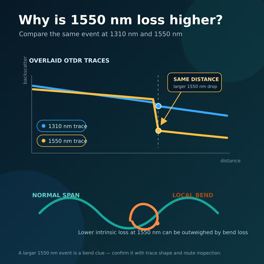
| Large event loss without a reflection peak | Bend, fusion splice or mode-field mismatch | Test both directions and inspect routing or splice records |
| First connector cannot be measured | Near-end dead zone | Add or lengthen the matched launch fiber |
| Last connector appears only as fiber end | No backscatter follows the event | Add a matched receive fiber |
| Values change with pulse width or wavelength | Test conditions changed | Restore the approved test recipe |
Reflectance Is Not Insertion Loss
Insertion loss measures forward power lost through a component or link. Reflectance measures power traveling backward.
A connector can pass its insertion-loss limit but fail a reflection requirement because of contamination, an air gap or damage. Another connection can have low reflection but high loss from misalignment or bending.
LuLeey’s PC, UPC and APC connector guide provides additional polish background, but the measured value and project specification still determine acceptance.
What to Confirm Before Choosing an OTDR
Record these requirements:
- Fiber type and test wavelengths
- Connector types and UPC/APC polish
- Link length, splitter topology and expected loss
- Required event spacing and dead-zone performance
- Event-reflectance range and accuracy
- Whole-link ORL range and report format
- Applicable standard and calibration evidence
- Dark-fiber or approved in-service test method
- Launch and receive fiber specifications
について LuLeey MINI OTDR page publishes wavelength, pulse-width, distance and dead-zone information for LL-OTDR-1000 configurations. The reviewed page does not publish a dedicated reflectance/ORL range or accuracy. Confirm those functions for the exact hardware and firmware before making a contractual claim.
Pair the chosen instrument with a correctly matched OTDR用ランチャーケーブルボックス.
実践的な次のステップ
最近のOTDRレポートを開き、すべての値を次のように分類してください。 イベント損失, イベント反射率/反射損失 または 全リンクORL. 各値の横に、符号の規則とマーカーの範囲を記録してください。.
LuLeeyに測定機器の点検を依頼する際は、ファイバーの種類、波長、コネクタの研磨状態、経路長、スプリッタの配置、必要な規格、許容範囲、およびサンプルレポートを提示してください。これにより、波長や距離のみに基づいてOTDRを選択するのではなく、機能レベルの検証が可能になります。.



 SFP/SFP+ (1G/2.5G/5G/10G)
 SFP-T (1G/2.5G/10G)
 AOCケーブル 10G/25G/40G/100G
 DACケーブル 10G/25G/40G/100G
 qsfp28 qsfp+ sfp28 100g/40g/25g
 銅線-光ファイバー・メディア・コンバーター
 ファイバーメディアコンバータPCBAボード
 OEOファイバー・メディア・コンバーター
 シリアル-ファイバー・メディア・コンバーター
 ビデオ-ファイバー・メディア・コンバーター
 1000m Gポン/エポン・オヌ
 10Gエポン・オヌ/XG-PON/XGS-PON
 2.5g Gpon/XponスティックSFP ONU
 ポー・グポン/エポン・オヌ
 ワイヤレスGPON/EPON ONT
 エポンOLT
 GPON OLT
 SFP PONモジュール
 産業用スイッチ
 マネージド・スイッチ
 POEスイッチ
 アンマネージド・スイッチ
 MTP/MPOファイバーケーブル
 光ファイバーカセット
 光ファイバーループバック
 光ケーブルとファイバーピグテール
 光スプリッターとスプリッターボックス
 ファイバーフランジコネクター
 光アダプター
 光減衰器
 クイックコネクターとコネクターパネル
 CATVアンプ
 CATV光受信機
 ビジュアル・フォルト・ロケーター
 OTDR
 光パワーメーター
 光ファイバー識別器
 光ファイバー・クリーナー
 ファイバー・クリーバー&ファイバー・ストリッパー
 銅工具


