Customs duties are the responsibility of customers, but standard logistics support DDP to most countries, duty-free such as US, DE, UK, CA, FR, IT, PL, AT, JP…



You inspect both connector endfaces, clean them, reconnect the link, and test again—but the loss is still too high. In this situation, fiber adapter loss is often blamed, yet the adapter is only one part of a mated connection. The real fault may be contamination inside the alignment sleeve, a damaged sleeve, incomplete seating, incompatible interfaces, or the test setup itself.
The quickest way forward is not repeated blind cleaning. Use a controlled substitution test: keep the cords, reference method, wavelength, and routing unchanged; replace only the adapter with a known-good unit of the exact same interface; then compare the result.

What “Fiber Adapter Loss” Really Means
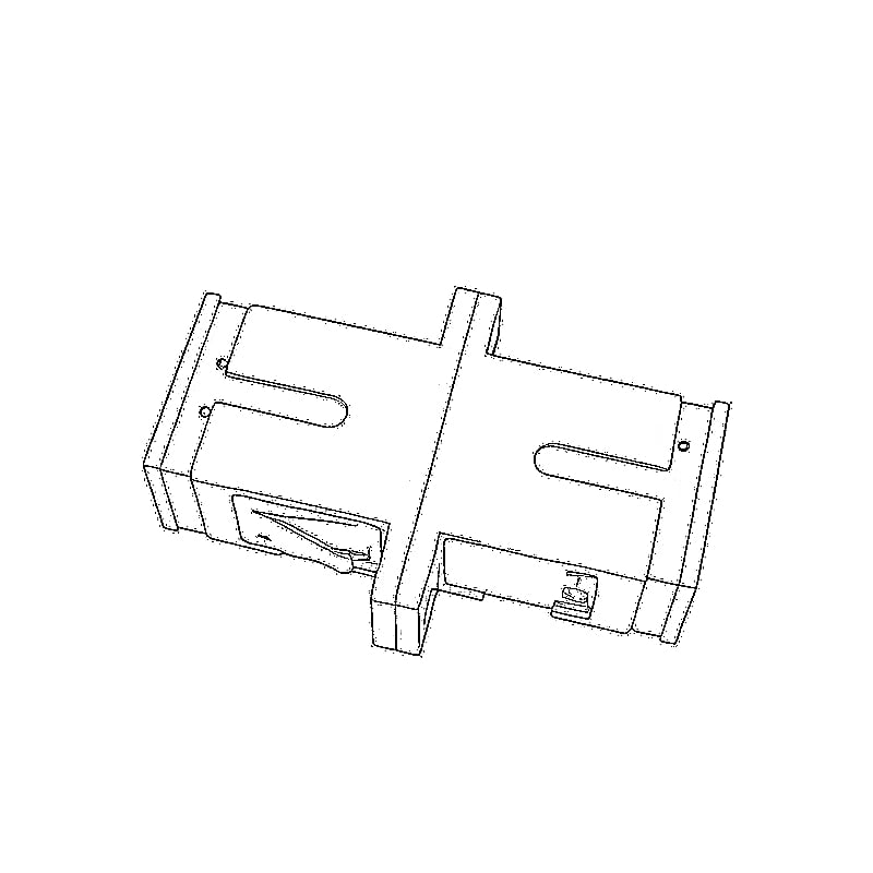
A standard passive adapter has no light source and no receiver. Its main job is to hold two connector ferrules in alignment. What a power meter sees is the loss of the complete mated connection: connector A, connector B, their endface geometry, the alignment sleeve, and the physical contact between them.
The Fiber Optic Association explains that a connector loss measurement is really a connection loss measurement of a mated pair. The alignment sleeve is part of that result, so one reading cannot automatically prove that the adapter alone is defective. A valid diagnosis must isolate variables.
This distinction matters when a technician says, “The adapter added 0.8 dB.” The reading may be repeatable, but it could still include a dirty reference connector, a damaged test cord, a poor reference, or an incompatible polish combination.
Why Fiber Adapter Loss Can Stay High After Cleaning
1. The alignment sleeve is contaminated
Cleaning the two visible endfaces does not guarantee that the sleeve inside the adapter is clean. Dust, dried residue, or wear particles can remain on the inner wall. When a ferrule is inserted, that material can move onto the ferrule or keep the two ferrules from reaching stable physical contact.
Repeated mating can make the symptom intermittent. One connection tests acceptably; the next is worse because the contamination moved.
2. The sleeve is worn, loose, chipped, or cracked
The split sleeve centers the ferrules. If it no longer holds them consistently, the fiber cores can be offset. A ceramic sleeve can also be damaged by angled insertion or excessive force. The adapter may look normal from outside while loss changes each time the connection is remated.
Do not assume a sleeve is good only because it is ceramic or new. Material and age are clues, not a pass result.
3. One connector is not fully seated
A connector can appear connected while its latch, bayonet, thread, shutter, or duplex clip prevents full seating. In a crowded panel, cable tension can also pull the connector slightly off-axis.
Insert the connector straight and stop when the normal latch or coupling mechanism is engaged. More force is not better. For threaded connectors, follow the equipment or connector instructions rather than tightening aggressively.
4. The interfaces are not actually compatible
Check the complete interface, not just the color or the fact that both ends “fit.” Confirm:
- Connector family: LC, SC, FC, ST, MPO/MTP, or another format
- Ferrule geometry and adapter type
- Fiber type required by the system
- Polish: UPC-to-UPC or APC-to-APC unless a specifically engineered conversion device says otherwise
- Simplex, duplex, keyed, shuttered, or hardened construction
Do not directly mate APC and UPC connector endfaces in an ordinary adapter. Their geometries do not form the intended physical contact and can create loss, reflection, or damage. Color is a useful field clue, but labels and specifications are the authority.
5. An endface is clean but physically damaged
“Clean” and “undamaged” are different results. A scratch, pit, chipped fiber, poor polish geometry, or damaged ferrule may remain after all contamination is removed.
IEC 61300-3-35:2022 explicitly separates visual inspection from optical qualification: inspection does not replace attenuation or return-loss measurement. A visually acceptable image therefore does not guarantee that the connection meets the link requirement.
6. The test setup is adding uncertainty
Before condemning the adapter, check the source wavelength, reference method, launch and receive cords, connector condition, and whether anything moved after the reference was set. Multimode testing also requires controlled launch conditions appropriate to the test standard.
IEC 61300-3-4:2023 describes methods for measuring attenuation of optical components. In field work, use the method required by the project or acceptance standard and keep that method unchanged during an A/B comparison.
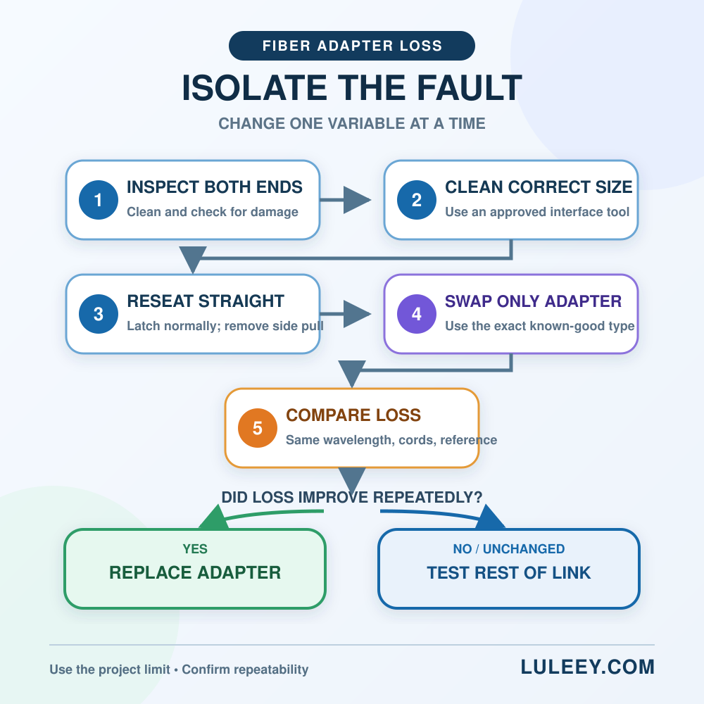
A Controlled Fiber Adapter Loss Troubleshooting Workflow
Step 1: Make the fiber safe
Disable or disconnect optical sources according to the approved network procedure. Never look into a fiber, connector, adapter, or microscope connected to an unknown source. Use suitable video inspection equipment and the required safety controls.
For a live production or PON link, schedule the work and follow the operator’s maintenance procedure before disconnecting anything.
Step 2: Record the baseline
Write down:
- Test wavelength
- Source and meter or OLTS/LSPM model
- Reference method and time of reference
- Launch and receive cord IDs
- Connector family and polish on both sides
- Measured loss and the project limit
- Whether the result changes after remating
Do not change several items at once. A useful troubleshooting test changes one variable.
Step 3: Inspect both mating endfaces
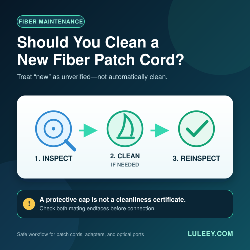
Remove both connectors from the adapter and inspect each endface with the correct video-probe tip. Look for contamination and physical damage. Clean only with a tool and method intended for that connector, then reinspect.
If you are unsure which round-ferrule cleaner size to use, see LuLeey’s 1.25 mm vs 2.5 mm fiber cleaner guide. Standard LC and MU interfaces normally use the 1.25 mm class; standard SC, FC, and ST interfaces normally use the 2.5 mm class. MPO/MTP needs a dedicated multi-fiber tool.
Step 4: Inspect and clean the compatible adapter interface
If the adapter design and maintenance instructions allow internal cleaning, use a lint-free tool made for the exact interface diameter. Keep the tool straight and use it only as directed. Do not insert a metal pin, sharp object, improvised cotton swab, or oversized cleaner.
For compatible recessed 1.25 mm interfaces, LuLeey lists the LCS125 CLEANSTICKS for LC/MU/MT as a dry, single-use tool. For compatible 2.5 mm interfaces, the LCS250 CLEANSTICKS for SC/ST/FC is also listed for one use per tube. Confirm access, shutters, polish, and the equipment maker’s cleaning procedure before use.
Do not force a tool into a hardened, shuttered, lensed, or unfamiliar optical port. If the internal construction is unclear, stop and obtain the manufacturer’s procedure.
Step 5: Reseat the pair correctly
Insert each connector straight, confirm the normal latch or coupling action, and remove cable tension near the adapter. Route the cord so it is not pulling sideways on the connection.
Test again without changing the reference or test cords.
Step 6: Substitute a known-good adapter
Use a known-good adapter that matches the original in connector family, polish support, fiber application, keying, and mounting format. Change only the adapter.
Repeat the measurement enough times to confirm that the improvement or failure is reproducible. If the result follows the adapter while all other variables remain fixed, the evidence against that adapter is strong.
Step 7: Measure, do not judge by appearance alone
Use an optical loss test set or stabilized light source and power meter for the insertion-loss result required by the project. An OTDR can help locate a reflective or lossy event on a sufficiently long link, but it does not replace the acceptance method specified for end-to-end loss.
The FOA’s connector and splice loss testing reference also emphasizes repeatability: loss can depend on both connectors and the alignment sleeve. A single surprising reading should be confirmed under controlled conditions.
How to Interpret the Results
| Observation | What it suggests | Best next action |
|---|---|---|
| Both endfaces pass inspection, and a known-good adapter gives a repeatable improvement | The original sleeve or adapter mechanics are a likely contributor | Remove the original from service and replace it with the exact compatible type |
| Loss changes significantly after every remating | Contamination transfer, poor seating, cable tension, or sleeve wear is possible | Inspect again, stabilize routing, and repeat the controlled adapter swap |
| The event has high reflection | An air gap, polish mismatch, damage, contamination, or poor seating may exist | Verify polish and seating; inspect both ends; measure with the required method |
| Cleaning the endfaces helps only briefly | The sleeve may be recontaminating the ferrules | Inspect or replace the adapter, then clean and recheck both connectors |
| Replacing the adapter makes no meaningful difference | The adapter is probably not the main fault | Check reference cords, terminations, splices, bends, wavelength, and test setup |
| Visual inspection passes but loss fails | Hidden geometry, alignment, contact, or measurement problems remain possible | Use the project’s optical test and isolate one component at a time |
“Meaningful difference” must come from the project limit, measurement uncertainty, and product specification. Do not use one universal adapter-loss number for every connector family and test method.
When to Clean and When to Replace the Adapter
Clean only when the interface is compatible with the approved tool and the adapter shows no sign of mechanical damage. Replace the adapter when any of these conditions applies:
- The sleeve is visibly chipped, cracked, deformed, loose, or displaced
- The connector will not seat or latch normally
- Loss is unstable after correct cleaning and routing
- A known-good adapter repeatedly restores the connection to its required limit
- The adapter has exceeded its documented service condition or mating-cycle requirement
- Contamination returns immediately after cleaned connectors are remated
An inexpensive adapter is not worth repeated service interruptions or damage to good reference cords. Tag the suspect unit so it does not return to the test kit or patch panel.
Choosing a Replacement Without Creating a New Fault
Match the replacement to the documented interface. Record the connector family, polish, fiber application, simplex or duplex arrangement, keying, flange or panel format, and any shutter or environmental features. Do not choose only by shell color or by a photograph.
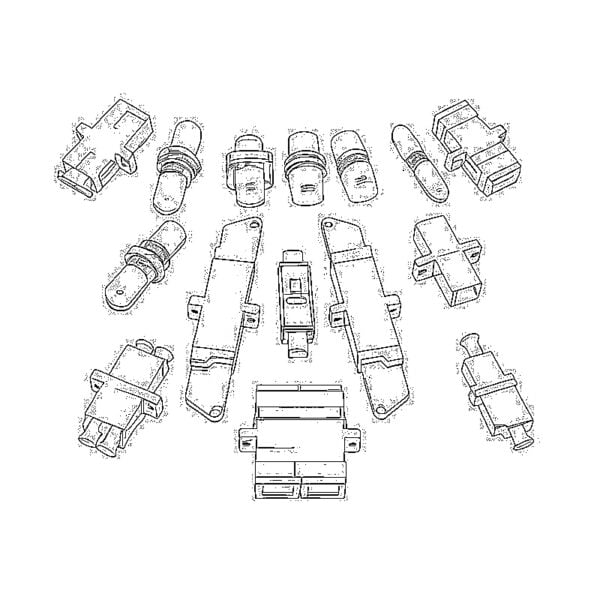
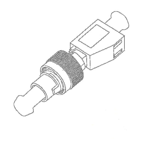
LuLeey’s optical adapters category includes standard and hybrid formats. Before ordering, compare the exact two interfaces and the published product specifications. A hybrid adapter that converts connector families is not automatically permission to mix APC and UPC polishes.
 SFP/SFP+ (1G/2.5G/5G/10G)
 SFP-T (1G/2.5G/10G)
 AOC Cable 10G/25G/40G/100G
 DAC Cable 10G/25G/40G/100G
 QSFP28 QSFP+ SFP28 100G/40G/25G
 Copper to Fiber Media Converters
 Fiber Media Converter PCBA Board
 OEO Fiber Media Converters
 Serial to Fiber Media Converters
 Video to Fiber Media Converters
 1000M GPON/EPON ONU
 10G EPON ONU/XG-PON/XGS-PON
 2.5G GPON/XPON STICK SFP ONU
 POE GPON/EPON ONU
 Wireless GPON/EPON ONT
 EPON OLT
 GPON OLT
 SFP PON Module
 Industrial Switches
 Managed Switches
 POE Switches
 Unmanaged Switches
 MTP/MPO Fiber Cables
 Fiber Optic Cassettes
 Fiber Optic Loopback
 Optic Cables and Fiber Pigtails
 Optical Splitters and Splitter Box
 Fiber Flange Connectors
 Optical Adapters
 Optical Attenuator
 Quick Connector and Connector Panel
 CATV Amplifier
 CATV Optical Receiver
 Visual Fault Locator
 OTDR
 Optical Power Meter
 Fiber Optic Identifier
 Fiber Optic Cleaners
 Fiber Cleavers & Fiber Strippers
 Copper Tools