Customs duties are the responsibility of customers, but standard logistics support DDP to most countries, duty-free such as US, DE, UK, CA, FR, IT, PL, AT, JP…





















































Yes, you can physically mix OM3 and OM4 fiber in many multimode links, and a short link may operate normally. Both are 50/125 µm laser-optimized Multimode Fibers. But a connector that mates and a link that comes up do not prove that the whole channel qualifies for OM4 reach.
The safe rule is: treat a mixed channel as a design that needs verification, not as an all-OM4 channel. For a new or critical installation, use one fiber grade throughout the operating channel, including trunks, patch cords and equipment cords.

What Happens When You Mix OM3 and OM4 Fiber?
The result depends on the Ethernet physical-medium specification (PMD), the length of each fiber segment, connector and splice loss, launch conditions, and the active equipment at both ends.
| Question | Practical answer |
|---|---|
| Can an OM3 connector mate with an OM4 connector? | Usually, if the connector format, polish and gender/pinning are compatible. Fiber grade alone does not determine whether two connectors mate. |
| Can the link come up? | It may, especially when the total path is comfortably within the OM3 limit and the optical channel is clean and correctly connected. |
| Does an OM4 trunk keep its full OM4 reach with an OM3 patch cord? | Not automatically. Do not claim the mixed channel as all-OM4 or apply the OM4 distance row without engineering evidence. |
| Is a mixed link a good choice for a new installation? | Usually no. A uniform grade is easier to specify, test, document and upgrade. |
| Does passing an insertion-loss test prove OM4 performance? | No. The test checks optical loss; it does not establish the channel’s modal bandwidth. |
OM3 and OM4: What Is the Same and What Is Different?
OM3 and OM4 share important physical characteristics:
- Both have a 50 µm core and 125 µm cladding.
- Both are optimized for laser transmission around 850 nm.
- Both may be supplied with LC, SC or MPO/MTP-style connectivity, depending on the cable assembly.
OM4 provides greater effective modal bandwidth at 850 nm. That higher bandwidth supports longer standardized reaches for some short-reach Ethernet PMDs.
Here are two useful examples from the IEEE 802.3 application table published by the TIA Fiber Optics Technology Consortium:
| Ethernet PMD | Active fibers | Maximum OM3 reach | Maximum OM4 reach |
|---|---|---|---|
| 10GBASE-SR | 2 | 300 m | 400 m |
| 40GBASE-SR4 | 8 | 100 m | 150 m |
These are maximum application distances for channels using the specified fiber grade and meeting the PMD’s channel conditions. They are not a promise that any cable of that color, or any mixed OM3/OM4 path, will reach the stated distance.
At 100G and above, names such as SR1, SR2, SR4 and VR use different lane arrangements and reach limits. Never choose a distance from the data rate alone. Identify the exact PMD printed in the optic documentation.
Why a Mixed Link May Work but Still Be a Poor Design
A successful link test answers only one question
When the link LED turns on, the receiver is detecting a usable signal at that moment. It does not show the bit-error margin, modal-dispersion margin or performance after temperature, contamination, connector movement or a future speed upgrade.
A link can therefore work at 10G today and still be a weak foundation for a later 40G migration.
Optical loss and modal bandwidth are different limits
Connector contamination, adapters, splices and fiber attenuation reduce received optical power. An optical loss test can reveal whether the measured loss is within the planned loss budget.
Modal dispersion is different. Light travels through multimode fiber in multiple modes, and the arriving pulses spread over distance. OM4 is designed to control that effect better than OM3 for supported 850 nm applications. A power meter cannot identify the fiber grade or prove that a mixed channel has OM4 bandwidth.
One OM3 segment does not create a simple arithmetic rule
It is tempting to say that one short OM3 patch cord automatically makes the entire channel OM3. That may be a useful conservative planning boundary, but it is not a complete engineering model. Mixed-fiber performance depends on the lengths and properties of the actual segments and the transmitter launch.
The more defensible statement is this: an OM3 segment prevents you from assuming the entire channel has uniform OM4 performance. If you need to use the extra distance available to OM4, replace the OM3 section or obtain a qualified design and test plan for the exact mixed channel.
Jacket color is an inventory clue, not proof
OM3 and OM4 assemblies are often color-coded differently by manufacturers, but color conventions are not a substitute for the printed cable legend, part number, order record or certification report. Some OM3 and OM4 products are both offered in aqua. A patch cord should not be classified from jacket color alone.
How to Check an Existing Mixed OM3/OM4 Link
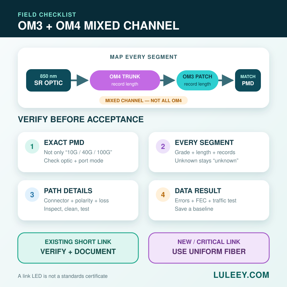
Use this process before accepting, extending or upgrading the link.
1. Identify the exact Ethernet PMD
Record the complete transceiver or port mode at both ends, such as 10GBASE-SR or 40GBASE-SR4. “10G,” “40G” or “100G” alone is not enough. Confirm that both ends use a compatible PMD, wavelength plan, lane count and connector arrangement.
2. Inventory every segment
List the fiber grade and length of:
- Equipment cords at both ends
- Horizontal or backbone trunks
- Harnesses, cassettes and breakout cables
- Any repair sections or undocumented jumpers
Use the printed cable legend and verified part records. Mark unknown segments as unknown rather than guessing.
3. Check connectivity, not just fiber grade
For duplex LC links, verify Tx-to-Rx polarity and the connector polish at every mating pair. For parallel-optic MPO links, verify the fiber count, connector gender/pinning, key orientation and polarity method.
LuLeey’s MPO cable buying guide organizes these choices into fiber type, connector, fiber count, gender, polarity and length. The separate MPO connector guide explains why a connector that fits mechanically can still have the wrong pin or polarity arrangement.
4. Compare the path with a conservative distance boundary
If any segment is confirmed OM3, do not use the all-OM4 maximum as a default design claim. For a short existing link, first compare the total path with the OM3 limit for the exact PMD. Keep margin for uncertainty and future changes.
If the path depends on the OM4-only part of the distance range—for example, more than 300 m for 10GBASE-SR or more than 100 m for 40GBASE-SR4—replace the OM3 section rather than assuming a short OM3 cord is harmless.
5. Inspect, clean and test optical loss
Inspect each connector end face with suitable fiber inspection equipment before mating. Clean only when needed, then reinspect. Measure the channel using the wavelength and test method appropriate to the cabling specification. Record the reference method, direction, test cords and measured loss.
This confirms cleanliness, continuity and loss performance. It does not convert a mixed channel into a certified OM4 channel.
6. Test actual data performance
Bring up the link in its intended port mode, then check more than the link LED:
- Receive-power readings, when supported and trustworthy
- CRC, symbol or code errors
- FEC corrected and uncorrected errors, when the PMD uses FEC
- Lane-by-lane status on parallel optics
- Error counters before and after a controlled traffic test
- Stability after patch cords are placed in their final routing
Save a baseline so later maintenance can distinguish a new fault from an existing weak margin.
7. Document the channel honestly
Label the path as mixed OM3/OM4, record the location and length of each grade, and state the PMD that was tested. Do not relabel an entire trunk or channel as OM4 because the visible patch cords are OM4.
Mixed OM3/OM4 Decision Guide
| Situation | Recommended decision |
|---|---|
| Short 10GBASE-SR link, one documented OM3 cord, total path well below 300 m, loss and traffic tests pass | It may remain in service. Document the mixed channel and do not claim all-OM4 reach. |
| 10GBASE-SR path longer than 300 m that relies on OM4 reach | Replace the OM3 segment and verify the complete channel before acceptance. |
| 40GBASE-SR4 MPO link with OM3 and OM4 sections | Verify the eight active fibers, MPO gender/pinning and polarity as well as distance and loss. Use 100 m as the conservative OM3 application boundary unless the exact mixed design is qualified. |
| Fiber grade or part history is unknown | Do not infer grade from color. Trace records, inspect the cable legend, obtain certification data or replace the unknown section. |
| New critical, backbone or upgrade-ready link | Use one specified fiber grade end to end, including patch cords. OM4 is the clearer choice when its reach or upgrade margin is required. |
Can an OM4 Patch Cord Be Used on an OM3 Link?
Often yes, provided the connector type, polish, polarity and all active-equipment requirements match. An OM4 cord does not downgrade the channel. However, it also does not upgrade the existing OM3 trunk to OM4 performance. Plan and label the link according to the weakest documented channel condition, then verify it for the intended PMD.
If you are replacing an MPO assembly, LuLeey lists separate 12-fiber OM3 MPO cable and 12-fiber OM4 MPO cable pages with configurable connector and polarity options. Match the replacement to the verified channel design; do not select it by OM3/OM4 name alone.

 SFP/SFP+ (1G/2.5G/5G/10G)
 SFP-T (1G/2.5G/10G)
 AOC Cable 10G/25G/40G/100G
 DAC Cable 10G/25G/40G/100G
 QSFP28 QSFP+ SFP28 100G/40G/25G
 Copper to Fiber Media Converters
 Fiber Media Converter PCBA Board
 OEO Fiber Media Converters
 Serial to Fiber Media Converters
 Video to Fiber Media Converters
 1000M GPON/EPON ONU
 10G EPON ONU/XG-PON/XGS-PON
 2.5G GPON/XPON STICK SFP ONU
 POE GPON/EPON ONU
 Wireless GPON/EPON ONT
 EPON OLT
 GPON OLT
 SFP PON Module
 Industrial Switches
 Managed Switches
 POE Switches
 Unmanaged Switches
 MTP/MPO Fiber Cables
 Fiber Optic Cassettes
 Fiber Optic Loopback
 Optic Cables and Fiber Pigtails
 Optical Splitters and Splitter Box
 Fiber Flange Connectors
 Optical Adapters
 Optical Attenuator
 Quick Connector and Connector Panel
 CATV Amplifier
 CATV Optical Receiver
 Visual Fault Locator
 OTDR
OTDR Optical Power Meter
 Fiber Optic Identifier
 Fiber Optic Cleaners
 Fiber Cleavers & Fiber Strippers
 Copper Tools


