Customs duties are the responsibility of customers, but standard logistics support DDP to most countries, duty-free such as US, DE, UK, CA, FR, IT, PL, AT, JP…





















































To calculate PoE Power Budget, add the maximum power demand that the switch must allocate to every powered device, then add a practical reserve for uncertain loads and future changes. The result must stay below the switch’s total PoE budget, while every device must also stay within the limit of its individual port.
That sounds simple, but many wrong calculations mix together four different numbers: device power consumption, power delivered at the switch port, cable loss and the switch’s own AC input. This guide separates them and gives you a repeatable method for cameras, Wireless Access Points, phones and access-control devices.
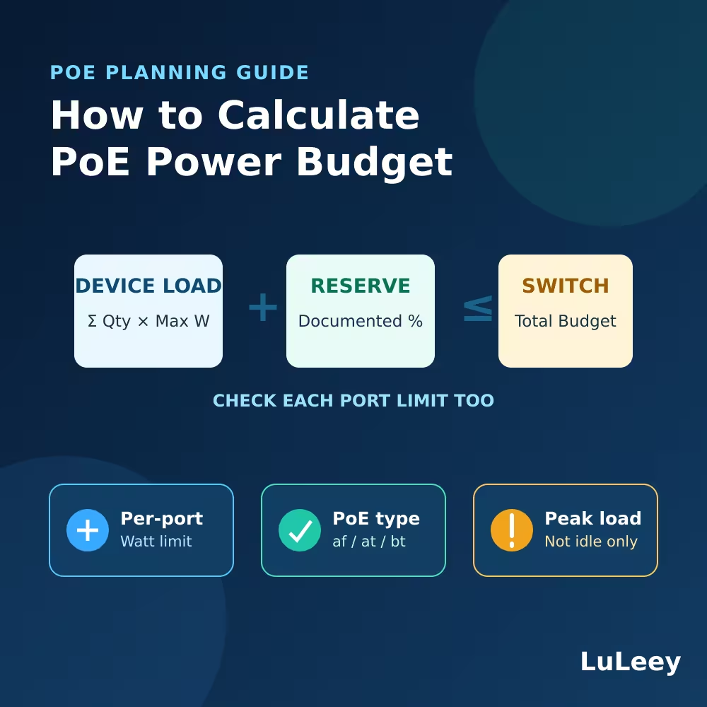
How to Calculate PoE Power Budget: The Formula
Use this planning formula:
Required PoE budget = sum of the planning watts for all powered devices + reserve
For repeated devices:
Required PoE budget = Σ(quantity × planning watts per device) × reserve factor
A reserve factor of 1.20 adds 20% headroom. That percentage is a planning choice, not an IEEE requirement. A well-documented fixed installation may use a different policy, while a project with uncertain device options, heaters or future expansion may need more.
Before using the formula, decide which wattage is valid for each device. Prefer, in this order:
- The maximum PoE allocation shown by the switch for the exact powered device.
- The device manufacturer’s maximum PoE input or requested power, with its measurement point clearly stated.
- The applicable PoE class allowance when no more precise verified value is available.
Do not design only from an idle power reading. A camera may draw more power when its infrared LEDs, heater or PTZ motor operates. An access point may peak during boot or under radio load.
Understand Per-Port Power and Total PoE Budget
A poe switch has at least two power limits.
| Limit | What it means | Example |
|---|---|---|
| Per-port limit | Maximum power one PoE port can provide | 30W on a PoE+ port |
| Total PoE budget | Maximum combined PoE power available across all ports | 400W for the whole switch |
Both conditions must be true:
- Each powered device must fit the selected port’s capability.
- All powered devices together must fit the total PoE budget.
For example, a 24-port switch rated at 30W per port and 400W total cannot provide 30W on all 24 ports at once. That would require 720W. It can still power 24 lower-power devices when their combined demand stays within 400W.
The number of PoE ports therefore tells you how many devices can be connected, not how many maximum-power devices can run simultaneously.
PSE Power Is Not the Same as PD Power
PoE uses two useful terms:
- PSE: Power Sourcing Equipment, such as the PoE switch.
- PD: Powered Device, such as a camera or access point.
Some power is lost as heat in the cable, so the power available at the PD is lower than the power the PSE may provide at its port.
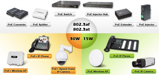
| PoE type | Common name | Maximum at PSE | Maximum available to PD |
|---|---|---|---|
| Type 1 | IEEE 802.3af / PoE | 15.4W | 13W |
| Type 2 | IEEE 802.3at / PoE+ | 30W | 25.5W |
| Type 3 | IEEE 802.3bt / PoE++ | 60W | 51W |
| Type 4 | IEEE 802.3bt / higher-power PoE | 90W | 71.3W |
These paired values explain why a device that needs 25W at its input may require a 30W Type 2 PSE port. The difference allows for worst-case delivery conditions, including cable loss.
Do not add a guessed cable-loss percentage on top of a class-based PSE value: that can count the same allowance twice. Add a separate cable allowance only when your calculation starts from a PD-side consumption figure and the relevant documentation or engineering method requires it.
The public Ethernet Alliance PoE technical brief lists these PSE and PD values. It also explains that IEEE 802.3bt Autoclass can help compatible equipment allocate power based on measured maximum PD demand, including factors such as cable loss and aging margin.
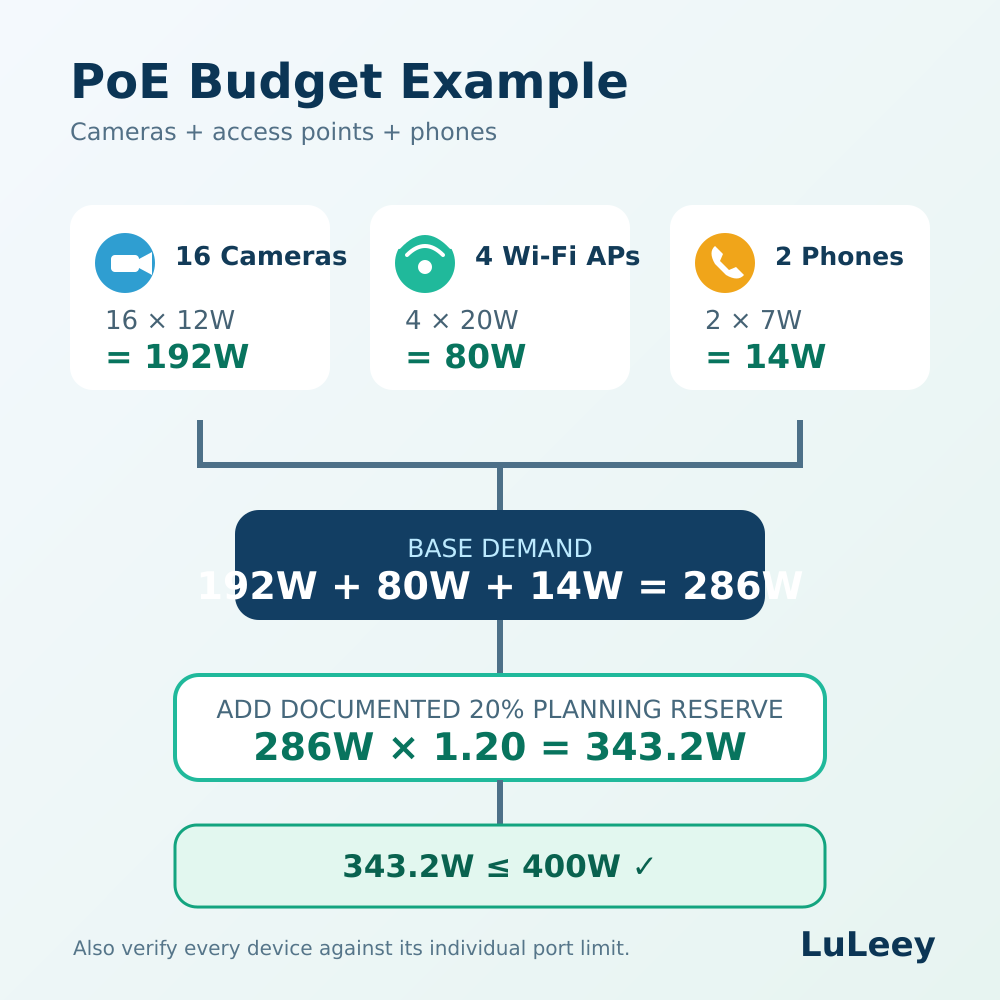
A Worked PoE Power Budget Calculation
Suppose a project uses:
- 16 fixed IP Cameras, each planned at 12W
- 4 wireless access points, each planned at 20W
- 2 VoIP phones, each planned at 7W
First calculate the base demand:
Cameras: 16 × 12W = 192W
Access points: 4 × 20W = 80W
Phones: 2 × 7W = 14W
Base total: 192W + 80W + 14W = 286W
Now apply a project planning reserve of 20%:
286W × 1.20 = 343.2W
A switch with a verified 400W PoE budget has 56.8W remaining under this planning method:
400W − 343.2W = 56.8W
The total fits, but the calculation is not finished. You must also confirm that every camera, access point and phone fits the power capability of its individual port and uses a supported IEEE PoE type.
If one device requires IEEE 802.3bt power, an IEEE 802.3af/at-only switch is not suitable for that device even when hundreds of watts remain in the total budget.
Which Device Wattage Should You Enter?
Use maximum demand for initial design
The safest planning value is normally the maximum power the device can request in its intended configuration, not its typical idle consumption.
Check optional loads and operating modes:
- IR illumination
- PTZ movement
- Camera heaters or blowers
- USB accessories powered by an access point
- Multiple active Wi-Fi radios
- Speaker or display operation on a phone or intercom
- Startup and firmware-update behavior
A device datasheet may list both “typical” and “maximum” figures. Use the maximum for capacity planning unless the manufacturer gives a more specific approved method.
Use switch allocation data when available
A managed switch may display actual consumption, requested class and allocated power separately. These are not always the same number.
Observed power helps with monitoring, but the switch may reserve more power than the device is drawing at that moment. When deciding whether additional devices can be safely added, use the switch’s allocation logic and power-management documentation rather than subtracting only the current live watt reading.
Do not assume every PoE+ device consumes 30W
“PoE+” describes a supported power type; it does not mean every connected device continuously consumes 30W. A compliant lower-power device may use much less.
However, when the exact request or maximum demand is unknown, using the applicable port-class value is more conservative than guessing from an idle measurement.
Why PoE Devices Work at First and Fail Later
An undersized power budget may not cause an immediate failure. Common symptoms include:
- Cameras reboot when infrared LEDs switch on at night.
- PTZ cameras disconnect while moving or heating.
- Access points restart when all radios become active.
- The last connected device is denied power.
- Lower-priority ports shut down when the budget is exhausted.
- Devices repeatedly power-cycle during a simultaneous restart after an outage.
These symptoms can also have other causes, including bad cabling, voltage drop, incompatible PoE modes, overheating, firmware problems or a failing power supply.
Check the switch log, PoE status, per-port allocation and event timing before blaming only the total wattage.
PoE Power Budget Checklist Before Buying a Switch
1. List every powered device
Record the exact model, quantity, PoE type, maximum power and any powered accessories.
2. Separate current devices from planned growth
Do not hide future devices inside a vague reserve. List known expansion separately, then add a reserve for what remains uncertain.
3. Check every port type
Confirm that the required ports support IEEE 802.3af, 802.3at or 802.3bt as needed. A high total budget cannot upgrade a port that supports only a lower power type.
4. Add the planning values
Multiply the quantity of each device model by its verified planning wattage, then add the groups.
5. Apply a documented reserve
Choose a reserve based on the project’s load uncertainty, environment, restart behavior and growth plan. Record the percentage so another technician can audit the calculation.
6. Compare against the PoE budget—not the AC input rating
The switch’s AC input or total system consumption includes its own electronics and conversion losses. Use the manufacturer’s stated PoE output budget for powered-device planning.
7. Check the data path too
Enough power does not guarantee enough bandwidth. Calculate camera bit rates, AP uplink demand, multicast behavior and uplink capacity separately.
Example with a LuLeey 24-Port PoE+ Switch
LuLeey’s 24 Port Gigabit PoE+ Managed Switch is specified with:
- 24 × 10/100/1000Mbps IEEE 802.3af/at PoE+ ports
- Up to 30W per PoE port
- 400W total PoE budget
- 2 × additional Gigabit RJ45 uplinks
- 2 × 1G SFP uplinks
For this model, any proposed device list must pass three independent checks:
- No device requires more than the supported IEEE 802.3af/at port can provide.
- The combined switch-side power allocation stays within 400W.
- The Gigabit access and uplink capacity suits the traffic design.
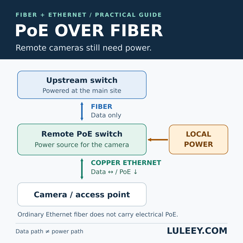
Its 1G SFP slots are fiber uplinks, not additional PoE ports and not 10G SFP+ ports. Selecting a fiber module is a separate task involving rate, wavelength, fiber type, connector and distance.
Final Answer
To calculate PoE power budget correctly:
- List every powered device and its verified maximum or allocated PoE demand.
- Multiply each device wattage by its quantity.
- Add the groups.
- Apply a documented planning reserve.
- Keep the result below the switch’s total PoE budget.
- Confirm that every individual device also fits its port’s PoE type and wattage limit.
Do not multiply every port by its maximum unless every connected device actually needs that class allocation. Do not rely only on typical or idle power either.
For a LuLeey project check, provide the exact device list, maximum power per device, cable lengths, required uplinks and planned expansion. That information allows both the PoE budget and network capacity to be reviewed before installation.

 SFP/SFP+ (1G/2.5G/5G/10G)
 SFP-T (1G/2.5G/10G)
 AOC Cable 10G/25G/40G/100G
 DAC Cable 10G/25G/40G/100G
 QSFP28 QSFP+ SFP28 100G/40G/25G
 Copper to Fiber Media Converters
 Fiber Media Converter PCBA Board
 OEO Fiber Media Converters
 Serial to Fiber Media Converters
 Video to Fiber Media Converters
 1000M GPON/EPON ONU
 10G EPON ONU/XG-PON/XGS-PON
 2.5G GPON/XPON STICK SFP ONU
 POE GPON/EPON ONU
 Wireless GPON/EPON ONT
 EPON OLT
 GPON OLT
 SFP PON Module
 Industrial Switches
 Managed Switches
 POE Switches
 Unmanaged Switches
 MTP/MPO Fiber Cables
 Fiber Optic Cassettes
 Fiber Optic Loopback
 Optic Cables and Fiber Pigtails
 Optical Splitters and Splitter Box
 Fiber Flange Connectors
 Optical Adapters
 Optical Attenuator
 Quick Connector and Connector Panel
 CATV Amplifier
 CATV Optical Receiver
 Visual Fault Locator
 OTDR
OTDR Optical Power Meter
 Fiber Optic Identifier
 Fiber Optic Cleaners
 Fiber Cleavers & Fiber Strippers
 Copper Tools


