Customs duties are the responsibility of customers, but standard logistics support DDP to most countries, duty-free such as US, DE, UK, CA, FR, IT, PL, AT, JP…





















































Yes. Optical Power can be too high for an SFP receiver. An SFP Receiver Overload occurs when the light entering the receiver is stronger than the maximum operating input specified for that module. The receiver may saturate, causing errors or an unstable link even though plenty of light is present.
This problem is most likely when a powerful long-reach single-mode transceiver is used over a very short, low-loss path. It can also appear in test benches, direct patch-cord connections, incorrectly designed links, or after a cable plant is simplified and loses much of its previous attenuation.
The safe response is not to choose a ranDOM attenuator. First identify the exact transmitter and receiver specifications, read or measure the received power, calculate the required loss, install a wavelength- and connector-compatible attenuator near the receiver, and measure again.
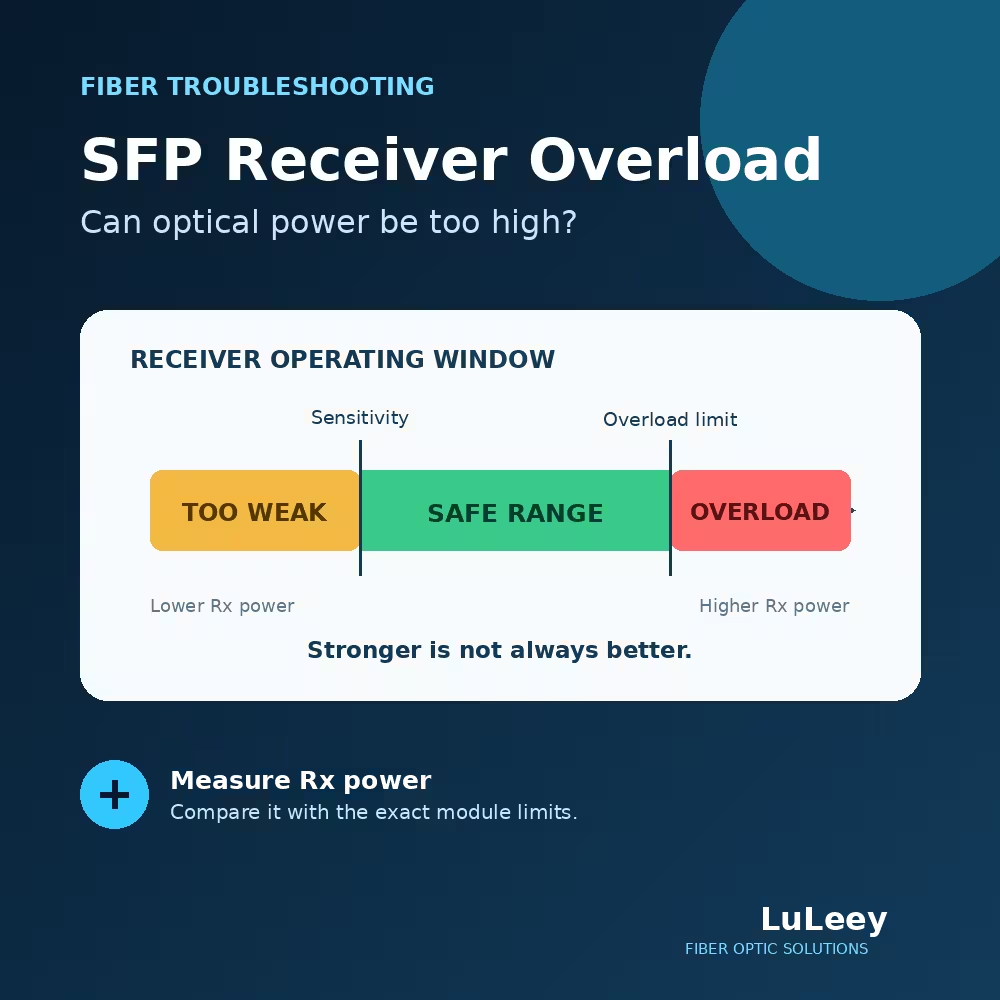
SFP Receiver Overload: Quick Diagnosis
| Finding | What it means | Next action |
|---|---|---|
| Rx Power is below receiver sensitivity | Signal may be too weak | Find excess loss, contamination, bends, bad splices or an insufficient link budget |
| Rx power is within the operating range | Power level is plausible | Check rate, wavelength, fiber, polarity, coding, errors and host compatibility |
| Rx power is above the overload limit | Receiver is outside its guaranteed operating range | Add calculated attenuation and retest |
| Rx power is near or above the damage threshold | Hardware risk may exist | Stop the test and follow the module vendor’s limit and safety procedure |
| DDM shows a high alarm but an external meter disagrees | Reading, calibration or measurement setup may be wrong | Verify wavelength, meter setup, module diagnostics and measurement point |
“Overload” and “damage threshold” are not the same specification. The overload value marks the upper boundary of normal receiver operation. A separate damage threshold, when supplied, marks a higher input that the receiver must not be exposed to.
Do not treat the space between them as a usable operating range.
Why Too Much Light Can Make a Fiber Link Worse
A fiber receiver converts optical pulses into an electrical signal. It needs enough light to distinguish ones and zeros from noise, but its photodetector and amplifier also have a finite operating range.
At the weak end, the receiver approaches its sensitivity limit and the bit-error rate can rise. At the strong end, the receiver can saturate and the waveform can become distorted.
The Fiber Optic Association describes these two boundaries as receiver sensitivity and receiver overload. Either insufficient or excessive received power can increase bit errors. FOA: Using Attenuators With Fiber Optic Data Links
This explains an unintuitive result: a stronger signal is not always a better signal. The goal is to keep received power comfortably inside the specified operating window.
Receiver Sensitivity, Overload and Damage Threshold
These three numbers answer different questions.
Receiver sensitivity
Receiver sensitivity is the lowest input power at which the module is specified to meet the relevant performance condition. The datasheet may tie this number to a particular bit-error rate, test pattern, line rate, temperature or FEC mode.
An Rx value below sensitivity is not guaranteed to work reliably.
Receiver overload
Receiver overload is the highest input power at which the module is specified to operate correctly.
Because dBm values are logarithmic, a less-negative number represents more power. For example, -3dBm is stronger than -10dBm.
If a module lists an overload limit of -7dBm, an input of -4dBm is 3dB stronger than that operating limit.
Receiver damage threshold
The damage threshold is a safety limit, not a performance target. A module can already be overloaded and unreliable well before the optical input reaches a level that risks permanent damage.
For a concrete example, Cisco’s public SFP-10G-ZR-I table lists receiver overload at -7dBm and a receiver damage threshold of +5dBm. The same datasheet requires an inline attenuator for that optic on single-mode links shorter than 40km. Cisco 10GBASE SFP+ Modules Data Sheet
Those values apply to that specific optic—not to every ZR, ER, LR, BiDi or third-party module.
Always use the datasheet for the exact part number and operating mode at both ends.
Why Long-Reach SFP Modules Can Be a Problem on Short Links
Long-reach optics are designed to overcome more fiber attenuation, connector loss, splice loss and other link penalties. They may launch more power and use a more sensitive receiver than a short-reach optic.
On the intended long route, the cable plant reduces the signal before it reaches the far receiver. On a one-meter or ten-meter test patch, much of that expected loss disappears.
The approximate relationship for one direction is:
Received power (dBm) = transmitter output (dBm) − total path loss (dB)
Suppose the actual transmitter output is +1dBm and the complete path loses only 2dB:
+1dBm − 2dB = -1dBm received power
If the far receiver’s overload limit is -7dBm, that input is 6dB above the specified maximum operating power. The link needs additional attenuation before normal operation can be expected.
Distance labels such as 40km or 80km do not by themselves tell you the minimum safe distance. The decisive values are transmitter output range, receiver overload, cable-plant loss and any minimum attenuation stated by the vendor.
Symptoms of High Rx Power
Receiver overload does not always produce the same symptom. Depending on the module and host, you may see:
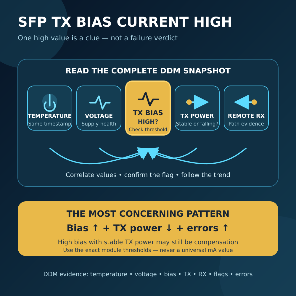
- A high-Rx warning or alarm in DOM/DDM data
- Link flapping or failure to establish a stable link
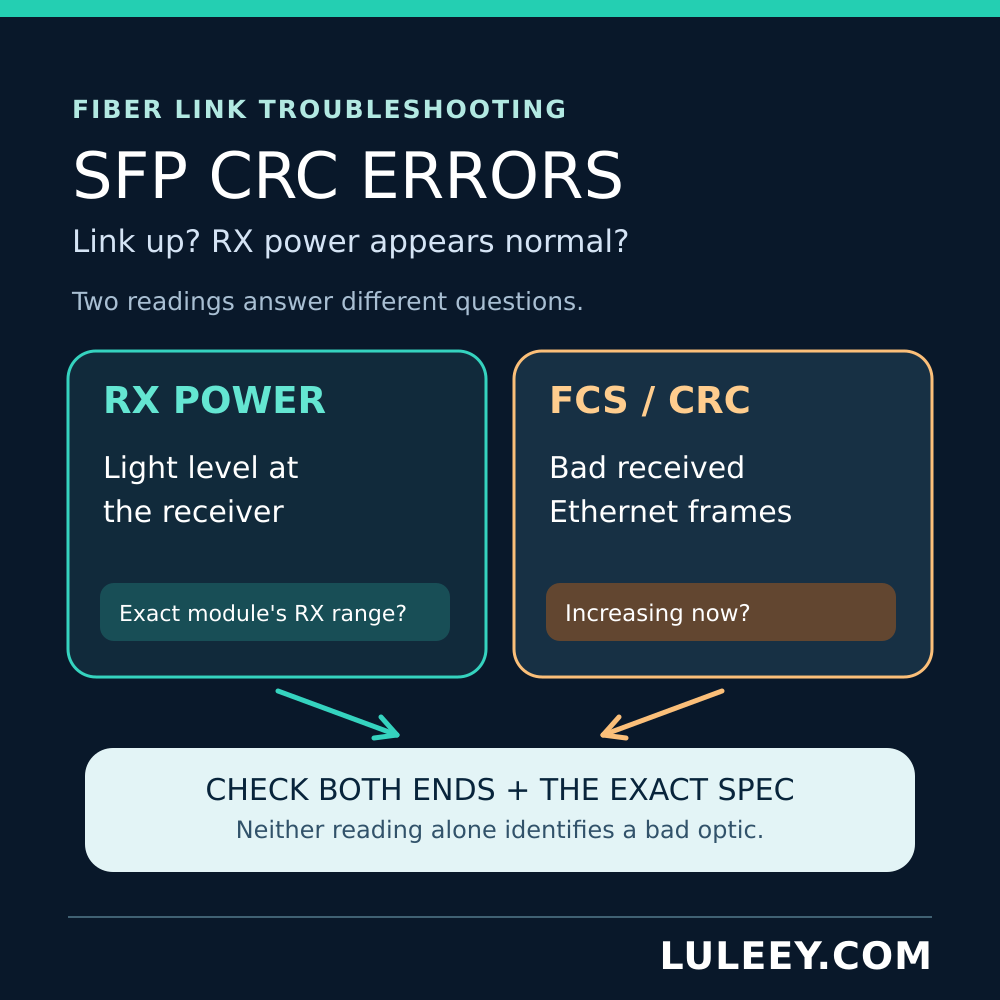
- CRC, FCS or symbol errors
- Packet loss that increases under traffic
- A link that works with a longer spool but fails with a short patch cord
- A problem that disappears after a suitable attenuator is inserted
These symptoms are not proof of overload. Dirty connectors, wrong wavelengths, mismatched rates, poor polarity, host incompatibility, excessive loss and faulty hardware can cause similar problems.
The diagnosis becomes credible only when the received power is compared with the exact receiver specification.
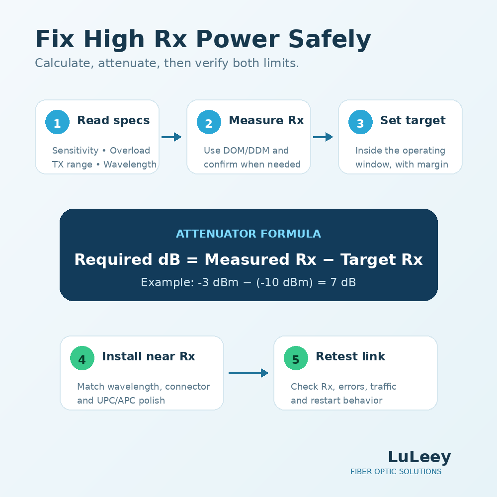
How to Check Whether Rx Power Is Too High
1. Record both endpoint models
Write down the exact switch or NIC, port, firmware, transceiver part number and module revision at each end.
Do not rely on a generic description such as “80km SFP+.”
2. Find the optical specification table
For each direction, locate:
- Minimum and maximum transmitter output
- Receiver sensitivity
- Receiver overload or maximum receiver input
- Damage threshold, if specified
- Operating wavelength
- Required minimum attenuation, if specified
- Conditions attached to the values, such as rate, BER, temperature or FEC
The two directions may use different modules or wavelengths, especially on a BiDi link, so calculate them separately.
3. Read DOM/DDM values
Many managed hosts report TX power and RX power. LuLeey’s DDM/DOM guide explains the diagnostic fields.
Compare the remote module’s TX power with the local module’s RX power for the same direction.
Do not subtract a module’s own TX and RX readings as if they belonged to one path; they represent opposite transmission directions.
4. Measure when the decision matters
DDM is useful for monitoring, but its accuracy depends on the module implementation and calibration.
For installation acceptance, a disputed alarm or a high-risk input, verify with an appropriate optical power meter set to the actual wavelength.
Disconnecting live fiber interrupts traffic and exposes active optical connectors. Follow laser-safety and equipment procedures, keep end faces clean, and never look into a fiber or transceiver.
5. Compare the result with the operating window
The received power should be above the sensitivity limit and below the overload limit, with engineering margin for:
- Measurement uncertainty
- Temperature changes
- Component aging
- Repairs and reconnections
- Future path changes
Do not design a permanent link exactly on either boundary.
How to Calculate the Required Attenuator
Use a target received power that sits safely inside the exact receiver’s operating range.
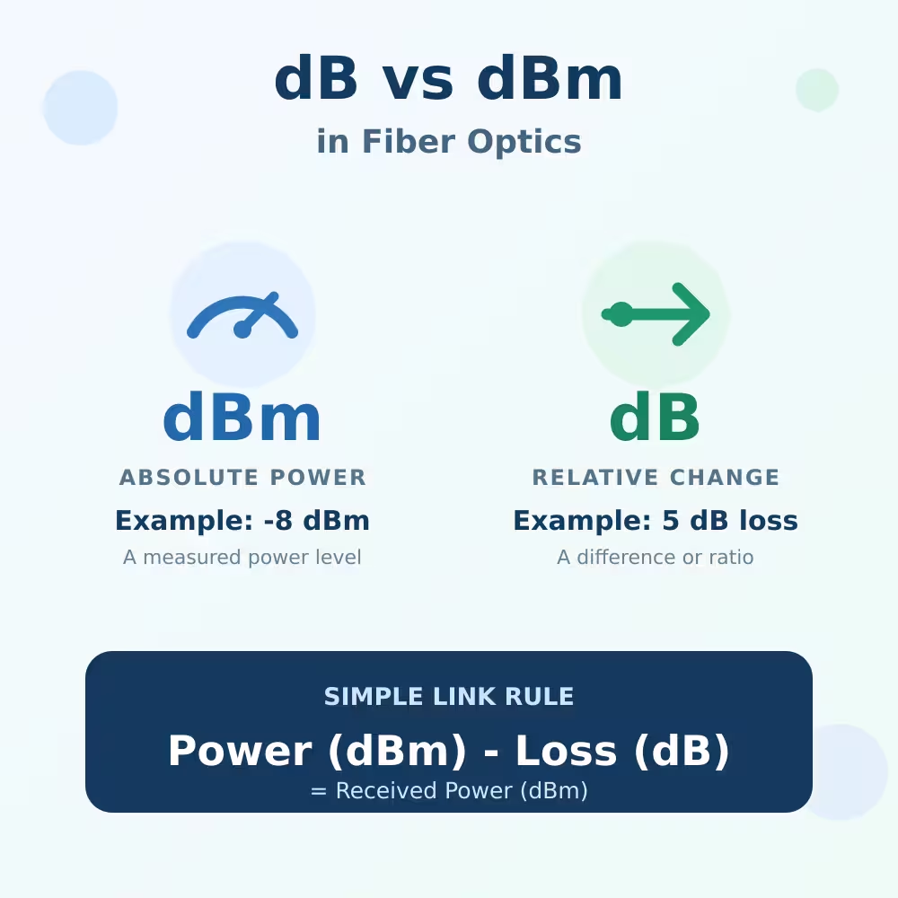
If the units are unfamiliar, read LuLeey’s dB vs dBm in fiber optics guide first: dBm describes an absolute optical power level, while dB describes gain or loss.
Required attenuation (dB) = measured Rx power (dBm) − target Rx power (dBm)
Example:
- Measured Rx power: -3dBm
- Receiver overload limit: -7dBm
- Chosen target after reviewing the module specification and link margin: -10dBm
Required attenuation = -3 − (-10) = 7dB
A 7dB attenuation would move the reading from approximately -3dBm to -10dBm:
-3dBm − 7dB = -10dBm
The target in this example is illustrative. It is not a universal recommendation. A real target must remain above receiver sensitivity after including all expected variations.
For a design-stage worst-case check, use the transmitter’s maximum output and the cable plant’s minimum expected loss:
Strongest expected Rx = maximum TX output − minimum path loss
Confirm that the strongest expected Rx remains below the overload limit after adding the selected attenuator.
Also test the weak end of the budget:
Weakest expected Rx = minimum TX output − maximum path loss − attenuator loss
The weakest expected Rx must remain above sensitivity with the required system margin.
An attenuator that fixes the strong case but breaks the weak case is not a valid design.
Where to Install an Optical Attenuator
The Fiber Optic Association recommends placing the attenuator near the receiver. This makes the final receiver power easier to measure and helps keep attenuator reflectance away from the transmitter. FOA attenuator guidance
For a duplex link, each direction has its own transmitter, fiber path and receiver. One receiver may need attenuation while the opposite direction does not.
If both directions are too strong, calculate and attenuate each receive path separately.
For a BiDi link, both directions share one fiber at different wavelengths. A single inline attenuator affects both wavelengths and both directions.
Verify the attenuator’s wavelength range and confirm that the added loss leaves both receivers inside their operating windows.
Fixed or Adjustable Attenuator?
Fixed attenuator
A fixed attenuator provides a predetermined loss. It is usually simpler for a permanent installation after the required value has been calculated and verified.
Adjustable attenuator
An adjustable attenuator is useful for laboratory testing, finding a stable target or simulating different link losses.
After adjustment, measure the actual received power rather than trusting only the dial or nominal setting.
LuLeey lists an LC UPC adjustable attenuator with 0–30dB adjustment for single-mode wavelengths from 1310 to 1550nm.
That page does not list 1270nm, 1577nm or every CWDM wavelength, so it should not be assumed suitable outside its stated range.
LuLeey’s optical attenuator category includes fixed and adjustable options with different connector and polish types.
Match the existing LC, SC or FC interface and UPC or APC polish. Do not mate UPC directly to APC.
Common Mistakes to Avoid
Choosing attenuation from distance alone
“80km module on a 1km link” indicates possible risk, but it does not calculate the required loss. Use actual specifications and measurements.
Treating every high Rx alarm as hardware damage
An overload alarm means the input is outside the operating range. It does not automatically prove permanent damage.
Check for a separate damage threshold and follow the vendor’s instructions.
Adding a large attenuator without checking sensitivity
Too much loss can move the receiver from overload to under-power. Calculate both the strongest and weakest expected conditions.
Attenuating the wrong direction
On duplex fiber, trace the path from the remote TX to the local RX. Each direction must be evaluated independently.
Ignoring wavelength and connector polish
An attenuator must support the operating wavelength and match the connector interface. A value that is correct in dB can still be the wrong component.
Relying on link-up alone
A link LED does not prove a healthy optical margin. Check actual speed, alarms, Rx power, traffic, packet errors and restart behavior.
Safe Verification Checklist
- Confirm the exact host and module part numbers at both ends.
- Save current port configuration, DOM readings and error counters.
- Find sensitivity, overload, damage threshold and TX output specifications.
- Calculate both directions separately.
- Measure received power at the actual wavelength when appropriate.
- Choose an attenuator that matches wavelength, fiber mode, connector and polish.
- Install it near the receiver unless the system vendor specifies otherwise.
- Reconnect with inspected and cleaned end faces.
- Confirm Rx power is safely inside the operating range.
- Clear counters, pass bidirectional traffic, and check errors over time.
- Restart or re-seat according to the equipment procedure and confirm the link returns normally.
- Record the final attenuator value, location and measured power.
Final Answer
Optical power can be too high. An SFP receiver needs light inside a defined operating window: above sensitivity but below receiver overload.
If a short single-mode link uses long-reach optics, compare the actual Rx power with the exact module’s overload limit. Calculate the required loss from a safe target, verify the weak end of the budget, install a matching attenuator near the receiver, and measure again.
Before choosing an attenuator from LuLeey, provide the two exact transceiver models, TX/RX specifications, measured power, wavelengths, connector polish and cable-path loss.
Those details are more useful than the distance label alone.

 SFP/SFP+ (1G/2.5G/5G/10G)
 SFP-T (1G/2.5G/10G)
 AOC Cable 10G/25G/40G/100G
 DAC Cable 10G/25G/40G/100G
 QSFP28 QSFP+ SFP28 100G/40G/25G
 Copper to Fiber Media Converters
 Fiber Media Converter PCBA Board
 OEO Fiber Media Converters
 Serial to Fiber Media Converters
 Video to Fiber Media Converters
 1000M GPON/EPON ONU
 10G EPON ONU/XG-PON/XGS-PON
 2.5G GPON/XPON STICK SFP ONU
 POE GPON/EPON ONU
 Wireless GPON/EPON ONT
 EPON OLT
 GPON OLT
 SFP PON Module
 Industrial Switches
 Managed Switches
 POE Switches
 Unmanaged Switches
 MTP/MPO Fiber Cables
 Fiber Optic Cassettes
 Fiber Optic Loopback
 Optic Cables and Fiber Pigtails
 Optical Splitters and Splitter Box
 Fiber Flange Connectors
 Optical Adapters
 Optical Attenuator
 Quick Connector and Connector Panel
 CATV Amplifier
 CATV Optical Receiver
 Visual Fault Locator
 OTDR
OTDR Optical Power Meter
 Fiber Optic Identifier
 Fiber Optic Cleaners
 Fiber Cleavers & Fiber Strippers
 Copper Tools


