Customs duties are the responsibility of customers, but standard logistics support DDP to most countries, duty-free such as US, DE, UK, CA, FR, IT, PL, AT, JP…





















































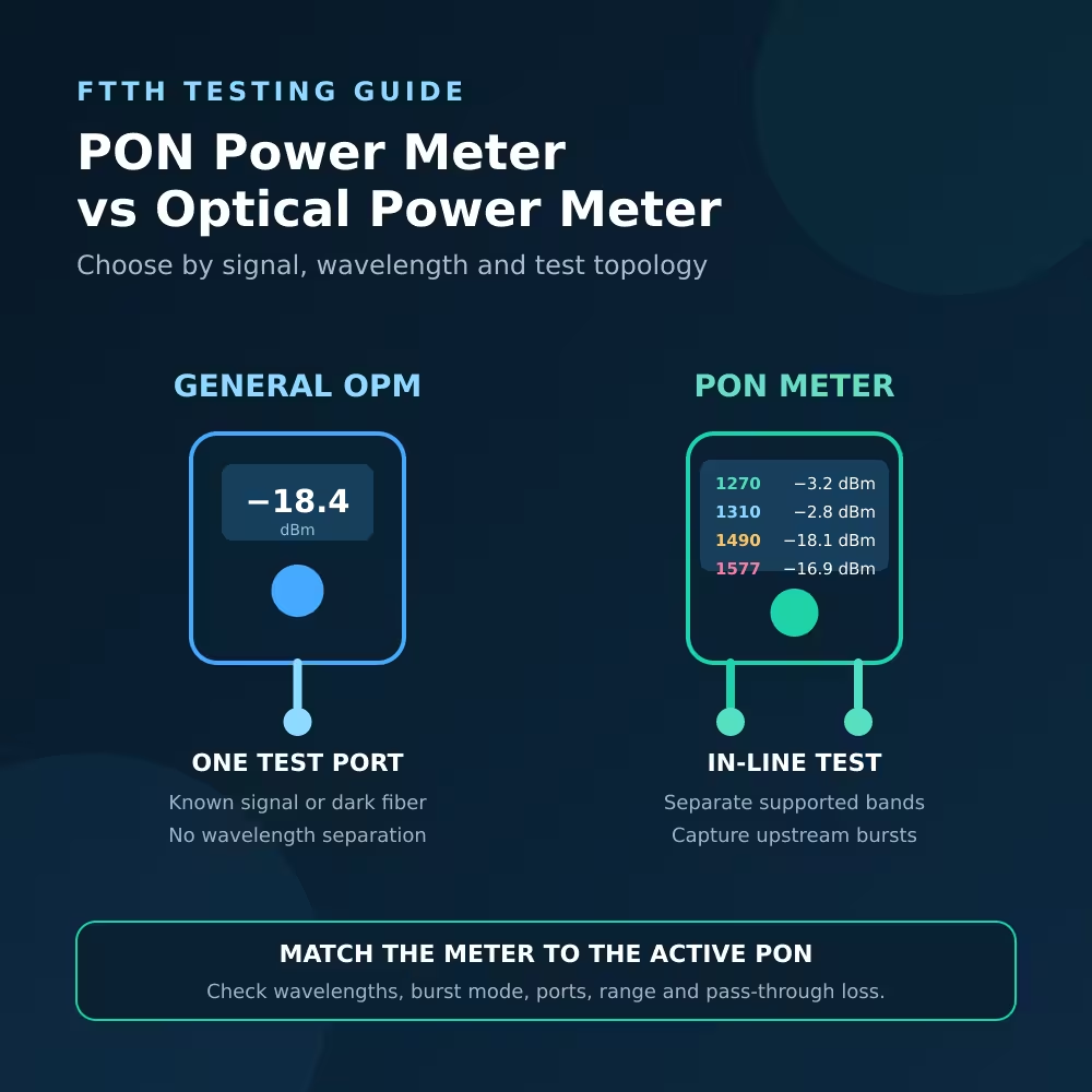
A regular Optical Power meter can test a live PON only in limited ways. It may measure a separated or disconnected downstream signal when its wavelength calibration, power range and connector interface match the job. It should not automatically be trusted to separate several wavelengths on the same fiber, remain transparently in line, or measure an ONU’s short upstream bursts.
This distinction matters because a wavelength button is not necessarily a wavelength filter. A conventional meter may let you select 1310, 1490 or 1577nm so it can apply the detector’s calibration factor for that wavelength. That selection alone does not prove that the instrument rejects the other active PON channels.
For per-channel measurements on an operating GPON or XGS-PON link, use a PON Power Meter whose specified passbands, isolation, through-path, burst response and connectors match the network. Confirm the exact ordered variant rather than relying on the words “PON meter.”
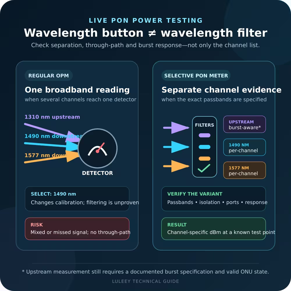
Can a Regular optical power meter Test a Live PON? Quick Answer
| Measurement question | Regular optical power meter | Wavelength-selective PON meter |
|---|---|---|
| Is optical power present from one isolated, known transmitter? | Often suitable when calibrated for that wavelength | Usually suitable if the channel and range match |
| What is the GPON downstream level at a disconnected ONU fiber? | Often possible, but service is interrupted and other wavelengths may affect the reading | Possible with the correct downstream channel |
| What are 1490 and 1577nm levels when GPON and XGS-PON coexist? | Not reliably separated unless filtering is explicitly specified | Use a model with both specified passbands and adequate isolation |
| What is the ONU’s scheduled upstream burst power? | Do not assume it can capture the burst | Use a meter with documented upstream burst measurement for that PON |
| Can the ONU remain connected and operational during the test? | Usually no through-path on a one-port meter | Possible only if the exact variant has the required in-line ports and method |
| Does a normal dBm reading prove that the ONU is registered? | No | No; registration and service require OLT/ONU checks |
| Can either meter locate a bend or splice by distance? | No | No; use an appropriate OTDR and procedure |
The deciding question is not “Does the screen list my wavelength?” It is “Can this instrument isolate and respond to the signal I need to measure without invalidating the test?”
Why PON Power Measurement Is Different
A PON carries signals in both directions over the same optical distribution network. Wavelength-division multiplexing separates upstream and downstream light, while time-division access coordinates transmissions from different ONUs.
For a single-fiber GPON system, ITU-T G.984.2 specifies 1480–1500nm downstream and 1260–1360nm upstream. Technicians commonly refer to these as 1490 and 1310nm channels. The standard also states that an ONU transmits upstream only when it is in an operating state and has been given a grant, and that upstream power measurement must account for the bursty signal.
The base XGS-PON wavelength plan in ITU-T G.9807.1 uses 1575–1580nm downstream and 1260–1280nm upstream, commonly labelled 1577 and 1270nm. Coexistence equipment can place GPON and XGS-PON channels on the same ODN.
The measurement problem therefore has three dimensions:
- Wavelength: Which optical channel must be measured?
- Direction: Is the signal sent continuously downstream or in scheduled upstream bursts?
- Topology: Will the meter terminate the fiber, or must traffic pass through it while the ONU stays connected?
A meter can support one dimension without supporting the other two.
A Wavelength Button Is Not Proof of Optical Separation
An optical detector’s response changes with wavelength. On many conventional optical power meters, selecting a wavelength tells the instrument which calibration coefficient to apply when converting detector current into a power value.
That is useful when only one known wavelength reaches the detector. It does not necessarily add a narrow optical filter in front of the detector.
Suppose an ODN simultaneously carries GPON downstream near 1490nm and XGS-PON downstream near 1577nm. A broadband detector can respond to both. Selecting “1490” may change the calibration calculation, but it does not prove the displayed result represents only the 1490nm channel.
A wavelength-selective PON meter instead specifies optical passbands and out-of-band isolation. Those specifications show whether the instrument is designed to separate coexisting services.
Before treating any meter as wavelength-selective, look for:
- A passband for each PON channel
- Isolation between those channels
- Measurement uncertainty for each channel
- The power range at each channel
- The number and function of optical ports
- Insertion loss through the live path
- Upstream burst response or capture method
If the datasheet lists only “calibration wavelengths,” “standard wavelengths” or a row of wavelength buttons, do not infer the missing filter specifications.
Why the Upstream Reading Is the Hard Part
The OLT continuously coordinates the PON. An ONU does not simply transmit a steady 1310 or 1270nm carrier whenever it is powered.
On GPON, an operational ONU sends upstream light in the time slots granted by the OLT. If you disconnect the ONU from the downstream signal and attach only a one-port meter, the ONU may lose synchronization and stop transmitting. Even while it is active, a slow meter may average the bursts, display an unstable value or miss them.
An appropriate burst PON power meter must observe the upstream transmission at the correct time while keeping the ONU connected to the OLT. Its display logic must also state what the result means—for example, average power during a detected burst rather than a long-term duty-cycle average.
Huawei’s official upstream optical-power measurement procedure says a functional ONU does not proactively transmit and calls for a burst optical power meter for upstream measurement. It also warns that instrument loss affects the optical path and that connectors should be cleaned.
That Huawei page contains an operational caution worth noticing: its tool description says the burst meter can measure without disconnecting a working line, while its “Impact on the System” section says services will be interrupted. Treat this as a reminder that in-line capability does not guarantee a non-disruptive procedure. Follow the network owner’s method for the exact platform, connection point and meter.
What a Regular Optical Power Meter Can Still Do
A conventional optical power meter remains useful. The important part is to choose a test that matches its design.
Measure one separated transmitter
If a known transmitter is connected directly to the meter and no other wavelength reaches the detector, select the correct calibration wavelength and confirm that the expected power is inside the meter’s range.
This is common when checking a continuous Ethernet optical transmitter or an isolated downstream PON source during an authorized test. The equipment’s transmit-power limits still determine whether the result passes.
Check downstream power at a disconnected ONU fiber
At the customer end, disconnecting the ONU may expose the downstream OLT signal to the meter. A regular meter can provide a useful reading when only the intended downstream wavelength is present and its calibration is suitable.
This method interrupts that subscriber’s optical connection. It also becomes ambiguous when another downstream service shares the fiber and the meter lacks channel-selective filtering.
Measure insertion loss on a dark fiber
With a matching stabilized light source, reference cords and an approved OLTS procedure, a regular power meter can measure end-to-end loss on a passive, dark link. That is a different task from measuring active PON channel power.
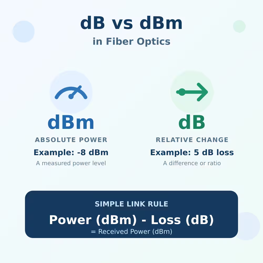
The result is normally expressed in dB relative to a reference. Active received power is normally expressed in dBm. Do not compare a dB link-loss value directly with a dBm receiver-power limit.
Confirm a large change, with limitations
A before-and-after reading can show that power changed after a documented action. Its uncertainty, wavelength ambiguity and connection repeatability still apply. Use it as supporting evidence, not as proof that every active channel is healthy.
When You Need a PON Power Meter
Use a wavelength-selective PON meter when the job requires any of the following:
- Separate GPON and XGS-PON downstream levels on a coexistence ODN
- Measure upstream burst power while the ONU remains active
- Measure upstream and downstream from an in-line connection point
- Apply channel-specific pass/fail thresholds
- Check 1550nm video or another overlay independently from PON data
- Record several PON channels in one maintenance workflow
The model must still match the actual network. A three-wavelength GPON meter designed for 1310/1490/1550nm does not automatically support 1270/1577nm XGS-PON. A downstream-only 1490/1577nm version does not automatically measure upstream bursts.
Likewise, “six wavelengths” is not enough information. Verify which channels are installed in that hardware variant, whether it has one or two optical ports, and whether the upstream measurement is specified for GPON, XGS-PON or both.
Insertion Loss Can Change a Live Link
An in-line meter is inserted into the ODN between the OLT and ONU. Its filters, couplers, connectors and internal fiber add loss in both directions.
If the link is already close to the receiver-sensitivity limit, inserting the meter can cause an ONU to drop offline or make the upstream burst too weak at the OLT. Dirty test connectors or an APC/UPC mismatch can add still more loss and reflection.
Before inserting the meter:
- Check the meter’s maximum insertion loss across every active channel.
- Confirm that the live link has enough margin for that added loss.
- Match the connector family and APC/UPC polish.
- Inspect and clean accessible interfaces using the approved method.
- Record the ONU state and optical readings before changing the path.
After the test, remove the instrument, restore the original connection and verify service. The meter’s own insertion loss should not be mistaken for a new ODN fault.
Do Not Reuse Generic Pass/Fail Thresholds
A PON meter may let you store thresholds and display PASS or FAIL. That feature is convenient, but the thresholds are only valid when they match the deployed system.
Limits can change with:
- PON generation and wavelength
- OLT and ONU optical class
- Measurement direction and location
- Split ratio and ODN design
- Coexistence or overlay elements
- Operator engineering margin
- Instrument uncertainty and insertion loss
For example, the acceptable downstream power at an ONU is not the same as the acceptable upstream burst power at the OLT. A threshold copied from another operator or optical class can produce a reassuring but invalid PASS result.
Record the numerical dBm value as well as the threshold profile. If the profile source cannot be identified, treat the colored status as unverified.
Why a Good Power Reading Does Not Prove Good Service
Optical power is only one part of PON operation. A channel can be inside its power window while the ONU remains offline because of:
- Authentication or serial-number policy
- Ranging or burst-reception problems
- An incompatible ONU profile
- Missing T-CONT or GEM mapping
- Incorrect VLAN configuration
- DHCP, PPPoE or upstream routing failure
- A failed ONU LAN interface
Conversely, an ONU can be online while a handheld meter shows a questionable value because the wrong channel, threshold profile or measurement mode was selected.
Use three kinds of evidence for a complete diagnosis:
| Question | Better starting evidence |
|---|---|
| How much power exists on each active PON channel? | Correct wavelength-selective or burst PON meter |
| Where is a bend, splice or break located? | Suitable OTDR and route/baseline data |
| Is the ONU activated and is the service provisioned? | OLT/ONU management, alarms and traffic tests |
One instrument does not replace all three.

An Eight-Step Live PON Power Test
Step 1: Identify the PON system
Record whether the network is GPON, EPON, XG-PON, XGS-PON or a coexistence system. Obtain the complete wavelength plan, including video or maintenance overlays.
Step 2: Define the measurement
State whether you need downstream power, upstream burst power, both directions, one channel or several simultaneous channels. Also identify the exact measurement point.
Step 3: Confirm live status and authorization
Treat the fiber as active until the network owner confirms otherwise. Determine whether the approved procedure is service-affecting.
Step 4: Verify the meter, not just its label
Check passbands, isolation, channel ranges, uncertainty, burst behavior, response time, port topology, insertion loss and connector polish for the exact hardware variant.
Step 5: Inspect and clean
Inspect accessible end faces and clean them with approved tools. Never look into a fiber or optical port.
Step 6: Connect in the documented direction
If the meter is in line, connect its OLT/network and ONU/user ports correctly. Confirm that the added loss will not push either direction outside its safe power window.
Step 7: Measure under a valid operating state
For upstream power, confirm that the ONU is activated and transmitting scheduled bursts. Save the numerical per-channel readings, threshold profile, meter mode, connection point and ONU state.
Step 8: Restore and validate
Remove the test instrument according to the approved procedure, reconnect the original path and confirm ONU registration, alarms and subscriber traffic.
Common Wrong Readings and Their Causes
| Observation | Likely explanation | First useful check |
|---|---|---|
| 1490 and 1577nm selections show similar values on a basic OPM | The wavelength selection may change calibration but not isolate channels | Check the datasheet for passbands and isolation |
| Upstream reads zero after the ONU is unplugged from the OLT | The ONU lost its downstream reference or has no grant | Use an approved in-line burst measurement method |
| Upstream value jumps or is much lower than OLT diagnostics | Meter response, burst definition or connection may not match | Confirm burst specification, ONU state and measurement point |
| Service drops when the PON meter is inserted | Added loss, contamination, connector mismatch or wrong port direction | Remove safely, restore service and audit the complete test path |
| The meter says PASS but the ONU is offline | Thresholds or physical power may be fine while activation fails | Check OLT alarms, authorization, ranging and profiles |
| The meter reads power but cannot locate the fault | Power meters do not report event distance | Use topology records and an appropriate OTDR workflow |
Change one variable at a time. A different meter, connection point, threshold profile and ONU state changed together cannot produce a useful comparison.
Choosing Between LuLeey’s Regular OPM and PON Meter
LuLeey’s LL-OPM-Li-G11 optical power meter page lists an InGaAs detector and standard wavelength selections of 850, 980, 1270, 1300, 1310, 1490, 1550, 1577 and 1625nm. It also lists SC, FC and ST connector support.
The current page does not publish channel passbands, inter-channel isolation, an in-line through path or upstream burst-response behavior. Therefore, treat those wavelength entries as conventional meter selections unless LuLeey supplies a datasheet confirming additional capabilities. Do not infer live multi-channel PON separation from the 1270 or 1577nm button alone.
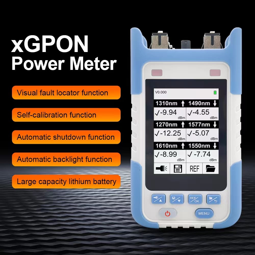
LuLeey’s XPOM002 XGS-PON optical power meter page lists selectable variants covering combinations of 1310, 1490, 1550, 1270, 1577 and 1610nm. Its specification includes channel passbands, mostly greater than 40dB isolation, ±0.5dB uncertainty and insertion loss below 1.5dB. The page describes it for live GPON, EPON and XGS-PON Testing and offers SC/APC or SC/UPC options.
Those page-level specifications still leave important order-specific questions:
- Which wavelength combination is installed in the exact unit?
- Does the selected version have an in-line OLT-to-ONU through path?
- What result definition and response time apply to GPON and XGS-PON upstream bursts?
- What are the valid power ranges at every selected channel?
- Which connector polish is supplied?
- Are operator thresholds available for the intended optical class?
The page notes that the 1490/1577 version has only one SC/APC connector, so that option should not be assumed to provide a two-port in-line upstream/downstream test. The page also does not state a burst-capture specification. Confirm these points with LuLeey before approving a meter for upstream acceptance testing.
Provide this information with a product inquiry:
- PON generation and coexistence architecture
- Required upstream and downstream channels
- Need for downstream-only or in-line testing
- OLT and ONU models and optical classes
- Expected power ranges at the test point
- Required burst-response method
- Connector family and APC/UPC polish
- Maximum permissible insertion loss
- Required threshold profiles and record format
Final Answer
A regular optical power meter can make useful measurements on a PON, but its wavelength buttons do not prove that it can test every channel on a live network.
Use a conventional OPM for an isolated known transmitter, a disconnected downstream check or a dark-fiber insertion-loss test when the calibration, range and method match. Use a wavelength-selective PON meter when you must separate coexisting channels, keep the ONU connected or capture scheduled upstream bursts.
Before connecting any meter:
- Identify the exact PON and wavelength plan.
- Define the channel, direction and measurement point.
- Check passbands and isolation—not only wavelength buttons.
- Verify upstream burst behavior and in-line port topology.
- Account for meter insertion loss and connector cleanliness.
- Use network-specific dBm limits and threshold profiles.
- Record the ONU operating state with every reading.
- Restore the link and validate registration and traffic.
When asking LuLeey to recommend a meter, send the PON generation, exact channels, OLT/ONU optical classes, connector polish, expected power range and whether upstream burst or non-disruptive in-line testing is required. Those details determine the correct variant more reliably than the wavelength list on the front panel.


 SFP/SFP+ (1G/2.5G/5G/10G)
 SFP-T (1G/2.5G/10G)
 AOC Cable 10G/25G/40G/100G
 DAC Cable 10G/25G/40G/100G
 QSFP28 QSFP+ SFP28 100G/40G/25G
 Copper to Fiber Media Converters
 Fiber Media Converter PCBA Board
 OEO Fiber Media Converters
 Serial to Fiber Media Converters
 Video to Fiber Media Converters
 1000M GPON/EPON ONU
 10G EPON ONU/XG-PON/XGS-PON
 2.5G GPON/XPON STICK SFP ONU
 POE GPON/EPON ONU
 Wireless GPON/EPON ONT
 EPON OLT
 GPON OLT
 SFP PON Module
 Industrial Switches
 Managed Switches
 POE Switches
 Unmanaged Switches
 MTP/MPO Fiber Cables
 Fiber Optic Cassettes
 Fiber Optic Loopback
 Optic Cables and Fiber Pigtails
 Optical Splitters and Splitter Box
 Fiber Flange Connectors
 Optical Adapters
 Optical Attenuator
 Quick Connector and Connector Panel
 CATV Amplifier
 CATV Optical Receiver
 Visual Fault Locator
 OTDR
OTDR Optical Power Meter
 Fiber Optic Identifier
 Fiber Optic Cleaners
 Fiber Cleavers & Fiber Strippers
 Copper Tools


