Customs duties are the responsibility of customers, but standard logistics support DDP to most countries, duty-free such as US, DE, UK, CA, FR, IT, PL, AT, JP…





















































SFP Rx Power different at both ends is often normal. The two receivers are not measuring the same transmitter through the same path: endpoint A receives light from B, while endpoint B receives light from A. Different transmitter launch powers, directional path loss and DDM measurement uncertainty can therefore produce different RX values even when the link is healthy.
The correct question is not, “Are the two RX numbers equal?” It is, “Is each receiver inside the permitted range for that exact transceiver, with adequate margin and no link errors?”
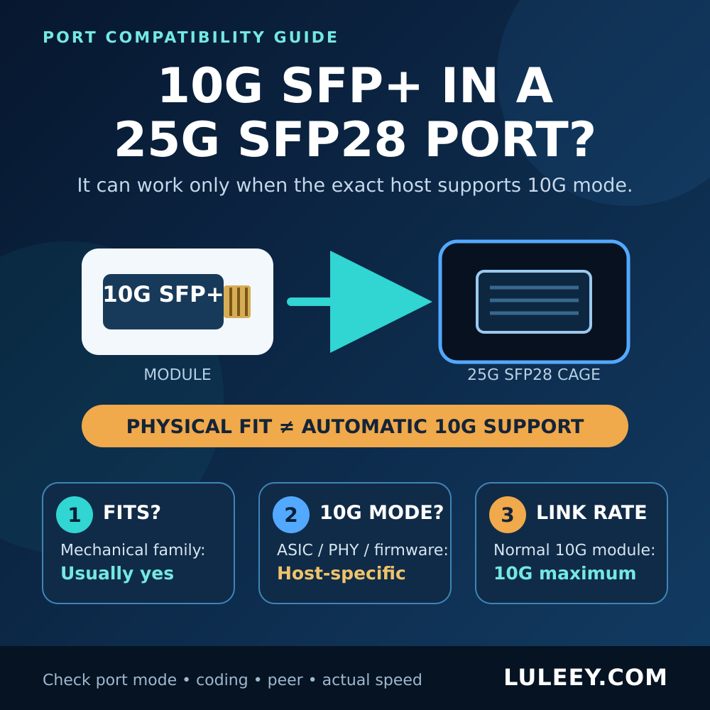
Scope: This guide covers point-to-point optical Ethernet links using SFP-family transceivers. It is not a compatibility verdict for a 2.5G PON ONU stick. For an ONU stick, verify the exact host cage, SerDes/PHY mode, firmware or driver, port setting, module coding, stick host mode, actual negotiated rate and resulting throughput.
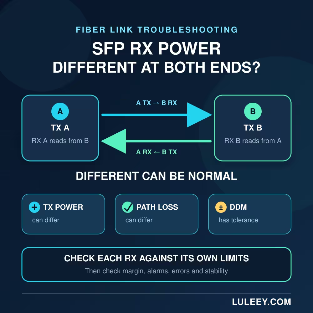
SFP RX Power Different at Both Ends: The Short Answer
Treat the link as two separate directions:
- A to B: A transmits; B receives.
- B to A: B transmits; A receives.
For a quick DDM estimate:
A-to-B apparent loss (dB) = A TX Power (dBm) − B RX power (dBm)
B-to-A apparent loss (dB) = B TX power (dBm) − A RX power (dBm)
Do not subtract A’s own TX from A’s own RX. Those values belong to opposite directions.
| Observation | First interpretation | Best next action |
|---|---|---|
| RX values differ, but both are inside their own limits, stable and error-free | Usually normal asymmetry | Record a baseline and monitor |
| One RX is near its low-warning or sensitivity limit | Low margin in the direction feeding that receiver | Check remote TX, connectors and that direction’s fiber path |
| One RX is near its high-warning or overload limit | The signal may be too strong for that receiver | Check its maximum input and the link design |
| DDM-estimated losses disagree more than expected | Different path loss, different launch power or DDM uncertainty | Clean and retest; verify with a wavelength-correct power meter |
| The gap changed suddenly or errors appeared | A real fault may be developing | Isolate one direction and compare with the earlier baseline |
Why the Two RX Values Do Not Have to Match
1. The two transmitters can launch different power
Even matched transceivers have a permitted TX-power range rather than one exact output. Temperature, component variation and aging can also shift launch power while it remains within specification.
If A launches more power than B, B may report a stronger RX value even when the A-to-B path has slightly more loss.
2. Duplex links use two separate fiber paths
A common full-duplex optical Ethernet link sends the two directions over two fibers. One strand can have a dirtier connector, tighter bend, weaker splice or different patch-panel route. The Fiber Optic Association describes common duplex links as two transceivers connected by two fibers carrying opposite directions. Link Testing
That means the A-to-B and B-to-A losses do not have to be identical.
3. BiDi links use different wavelengths
A BiDi pair carries both directions on one strand, but A and B transmit at complementary wavelengths. The two transmitters may have different launch-power ranges, and fiber plus passive components can have wavelength-dependent loss. Each module’s internal monitor can also have different calibration behavior.
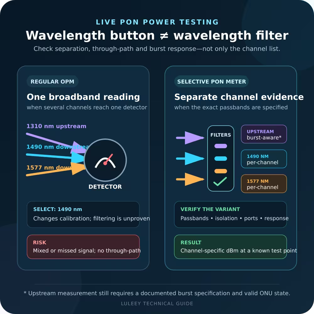
Before interpreting BiDi readings, confirm the exact paired wavelengths and test conditions. LuLeey’s BiDi SFP optical power test guide explains why a regular broadband power meter should measure one known transmitter at a time rather than being treated as a live per-wavelength separator.
4. DDM is diagnostic telemetry, not a certified loss test
The current SNIA SFF-8472 specification defines TX and RX optical-power diagnostics. For the vendor-specified wavelength and required operating range, it says TX and RX accuracy must be better than ±3 dB under the specified temperature and voltage conditions. RX may represent average received power or optical modulation amplitude, depending on the module’s declared mode. members.snia.org
That tolerance is much wider than the 0.01 dB resolution some hosts display. Two modules can therefore show tidy decimal values without those values being laboratory-grade measurements. TX and RX diagnostic uncertainties also compound when they are subtracted to estimate path loss.
Use DDM for rapid checks, alarms and trends. Use a calibrated, wavelength-appropriate external instrument when the decision depends on a precise power or loss measurement. LuLeey’s DDM/DOM guide covers the five common diagnostic fields and their practical use.
A Two-Direction Example
Suppose a link reports these illustrative values:
| Direction | Remote TX | Local RX | DDM-estimated apparent loss |
|---|---|---|---|
| A to B | −1.0 dBm at A | −4.0 dBm at B | 3.0 dB |
| B to A | −3.0 dBm at B | −5.0 dBm at A | 2.0 dB |
The RX readings differ by 1 dB, but that number alone says little. The transmitters start 2 dB apart, and the two DDM-estimated path losses differ by 1 dB. Both directions might still be comfortably inside their exact receiver ranges.
These values are an example, not universal limits. The real pass/fail decision must use the specifications and thresholds for each installed module.
How to Troubleshoot Unequal SFP RX Power
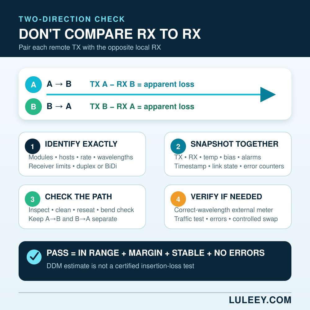
Step 1: Record the exact equipment and operating mode
For both ends, write down:
- Host manufacturer, model, slot and port
- Firmware, operating system or driver version
- Transceiver manufacturer, exact part number and revision
- Configured and negotiated rate
- Fiber type, connector type and polish
- Duplex or single-fiber BiDi construction
- TX and RX wavelengths
Do not decide compatibility from the words SFP, SFP+, SFP28 or a headline speed. The physical cage, host SerDes mode, supported signaling mode, firmware, module coding and actual negotiated rate all matter.
Step 2: Capture both DDM snapshots at the same time
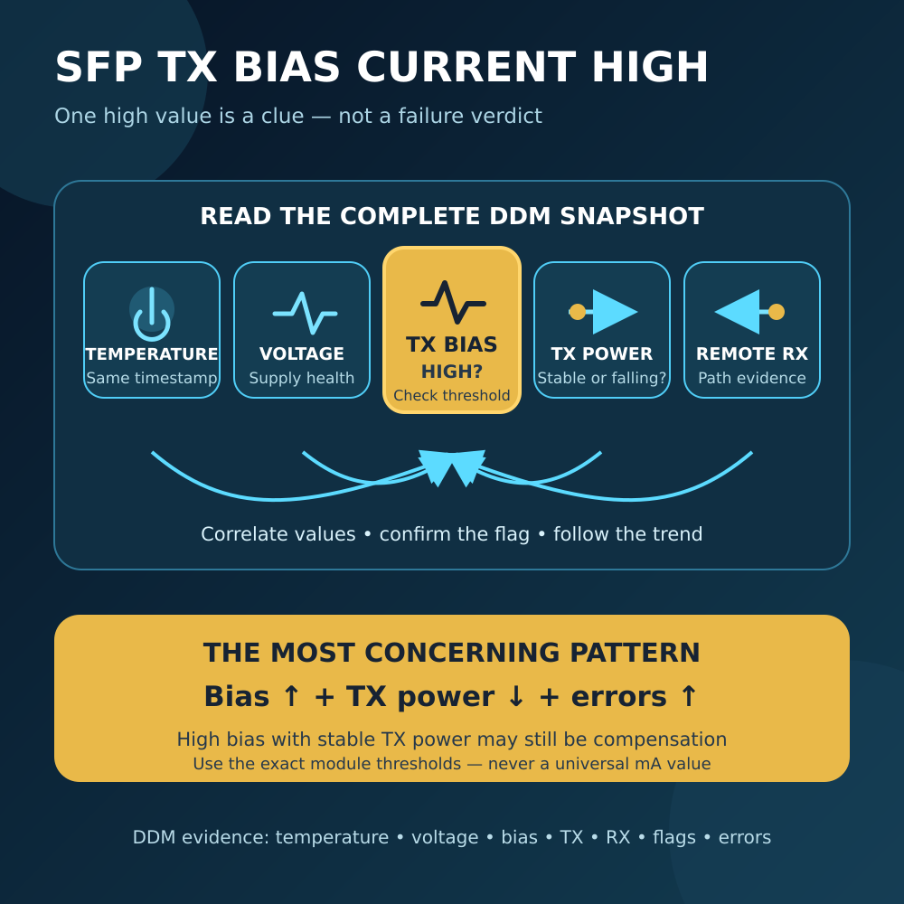
Record TX power, RX power, temperature, supply voltage, laser bias current and every warning or alarm at both ends. Also save interface error counters and link-flap history.
Near-simultaneous readings matter because temperature and operating state can change. If possible, save the raw command output or management screenshots with a timestamp.
Step 3: Compare each RX value with its own limits
Use the exact receiver’s published minimum operating power, sensitivity or low alarm, and maximum input or overload limit. Do not compare both ends against one generic “good dBm” range.
A stronger reading is not automatically better. Too much Optical Power can overload a receiver; LuLeey’s SFP receiver-overload guide explains the high-power side of the window.
Step 4: Calculate each direction separately
Pair the remote transmitter with the local receiver:
- A TX with B RX
- B TX with A RX
Subtract in dB as shown above, but label the result DDM-estimated apparent loss. It includes two independent diagnostics and is not an acceptance-grade insertion-loss measurement.
Compare like with like. Do not compare a TX value from one time or temperature with an RX value captured much later under different conditions.
Step 5: Inspect and clean before replacing hardware
Follow an inspect-clean-inspect process on every accessible connector. Verify that connector polish matches at every physical mating point, reseat adapters correctly and check the cable route for tight bends, crushing or tension.
On a duplex link, keep the two strands identified. A problem on the A-to-B strand should mainly affect B’s RX; a problem on the B-to-A strand should mainly affect A’s RX.
Step 6: Verify power with an external meter when needed
Never look into an active transceiver or fiber; optical radiation may be invisible. Work in an approved maintenance window and make sure the meter can safely accept the expected power.
For each direction:
- Confirm the remote TX wavelength and expected power range.
- Use a compatible calibrated power meter, correct adapter and clean reference jumper.
- Set the meter to the documented wavelength or an explicitly supported setting.
- Isolate one transmitter and measure its launch power.
- Measure arriving power at the far end with the receiver disconnected.
- Subtract the two external readings to estimate installed-path loss.
FOA recommends measuring at the proper wavelength and notes that receiver power depends on both transmitter launch power and path attenuation. Its measurement guidance also warns that meter calibration, autoranging, physical movement and wavelength mismatch contribute uncertainty. Link Testing
Step 7: Check traffic quality, not power alone
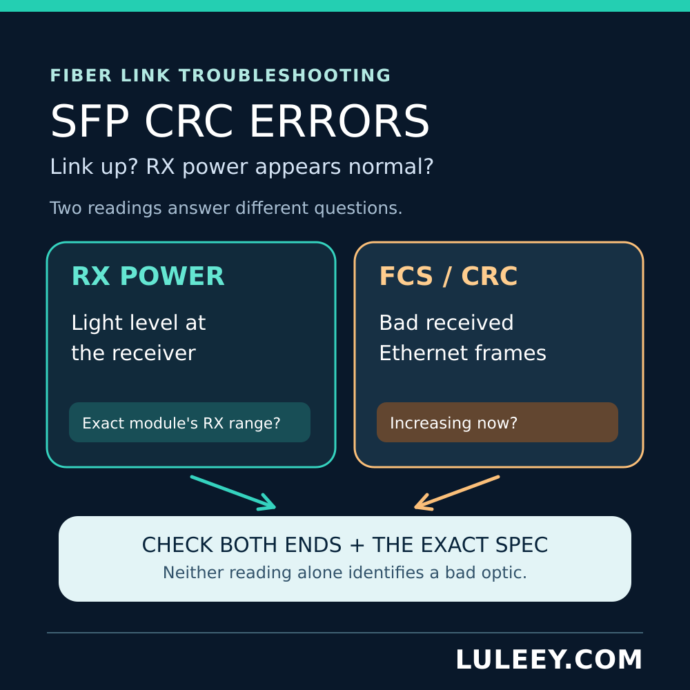
An RX value inside range does not prove error-free transmission. Check CRC/FCS errors, symbol or PCS errors where available, drops, link flaps and a controlled traffic test.
If errors continue while RX appears normal, follow LuLeey’s SFP CRC errors with normal RX power guide. Dirty or damaged connectors, reflections, wrong fiber type, incompatible optics, host-side electrical issues and marginal signal quality can exist without an obvious average-power alarm.
Step 8: Swap one variable at a time
If a fault remains, change only one element per test: jumper, path strand, transceiver or host port. Keep rate, firmware and operating mode controlled. Changing several items together may restore service but will not identify the cause.
When Is the Difference a Real Problem?
Investigate further when any of these is true:
- One receiver is outside, or too close to, its exact low or high limit.
- RX low/high warnings, RX LOS or link flaps occur.
- CRC/FCS, symbol or PCS errors rise under traffic.
- The difference changes suddenly from a stable baseline.
- One directional DDM-estimated loss becomes much worse than the other and the physical construction does not explain it.
- An external, wavelength-correct measurement confirms unexpected directional loss.
- The symptom follows one transceiver during a controlled swap.
Do not use a universal rule such as “more than 1 dB is bad” or “both ends must be within 0.5 dB.” The acceptable difference depends on the two launch-power ranges, both receiver windows, wavelength, path construction, measurement uncertainty and required engineering margin.
A Better Pass/Fail Rule
A link is in a defensible state when:
- Both endpoint modules and host modes are explicitly supported.
- Each RX value is inside that receiver’s specified operating window with appropriate margin.
- No relevant warning, alarm or loss-of-signal state is active.
- Interface error counters remain stable during a representative traffic test.
- The readings are stable relative to the link’s own baseline.
- Any unexplained large asymmetry has been checked with an independent, wavelength-correct measurement.
Equality is not the goal. Adequate margin, stability and error-free service are.


 SFP/SFP+ (1G/2.5G/5G/10G)
 SFP-T (1G/2.5G/10G)
 AOC Cable 10G/25G/40G/100G
 DAC Cable 10G/25G/40G/100G
 QSFP28 QSFP+ SFP28 100G/40G/25G
 Copper to Fiber Media Converters
 Fiber Media Converter PCBA Board
 OEO Fiber Media Converters
 Serial to Fiber Media Converters
 Video to Fiber Media Converters
 1000M GPON/EPON ONU
 10G EPON ONU/XG-PON/XGS-PON
 2.5G GPON/XPON STICK SFP ONU
 POE GPON/EPON ONU
 Wireless GPON/EPON ONT
 EPON OLT
 GPON OLT
 SFP PON Module
 Industrial Switches
 Managed Switches
 POE Switches
 Unmanaged Switches
 MTP/MPO Fiber Cables
 Fiber Optic Cassettes
 Fiber Optic Loopback
 Optic Cables and Fiber Pigtails
 Optical Splitters and Splitter Box
 Fiber Flange Connectors
 Optical Adapters
 Optical Attenuator
 Quick Connector and Connector Panel
 CATV Amplifier
 CATV Optical Receiver
 Visual Fault Locator
 OTDR
OTDR Optical Power Meter
 Fiber Optic Identifier
 Fiber Optic Cleaners
 Fiber Cleavers & Fiber Strippers
 Copper Tools


