Customs duties are the responsibility of customers, but standard logistics support DDP to most countries, duty-free such as US, DE, UK, CA, FR, IT, PL, AT, JP…





















































To test an SFP port with a Fiber Loopback, connect the optical transmitter back to the receiver through a correctly matched passive fiber path. The result can help isolate the local host port, transceiver and connector path from the remote fiber plant and peer device.
It is a narrow diagnostic, not a complete link certification. A loopback that clears LOS or brings the interface up does not prove the remote cable, the far-end device, VLAN configuration or production interoperability. Before connecting anything, also confirm that the returned optical power cannot exceed the receiver’s maximum operating input.
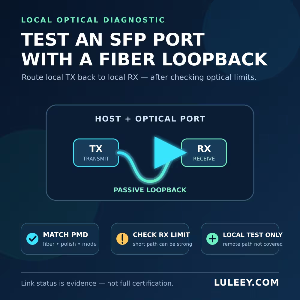
Test an SFP Port with a Fiber Loopback: What It Covers
A duplex optical transceiver has a transmit side and a receive side. A passive duplex loopback routes:
local TX → short fiber path → local RX
Depending on the host, PHY, Ethernet PMD and port configuration, the device may clear RX LOS, report receiver lock or show Link Up. Some platforms need a dedicated diagnostic mode or a second port, so Link Up is not guaranteed for every valid local optical loop.
The test can exercise these local elements under the test conditions:
- The host’s ability to recognize and power the module
- The module’s optical transmitter and receiver
- The loopback connector and short fiber path
- Enough of the host electrical/SerDes path to produce the observed status
It does not exercise the production trunk, patch panels, splices, remote transceiver or remote host. It also does not automatically generate or verify useful Ethernet traffic. A switch may not send a frame out a port and accept the same frame back as a normal end-to-end test. Packet testing requires a platform-supported diagnostic, traffic generator or documented test method.
1. Match the Loopback to the Exact Optical Interface
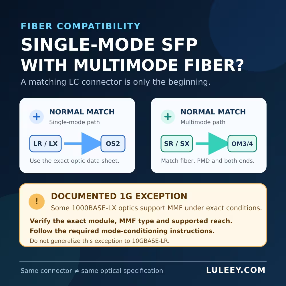
Start with the transceiver part number and its data sheet. Match the loopback’s connector, polish and fiber type to the optical PMD—not merely to the metal module format.
For example, a typical duplex 10GBASE-SR optic uses multimode fiber, while a typical duplex 10GBASE-LR optic uses single-mode fiber. IEEE 802.3 defines different physical-medium specifications for different Ethernet rates and media; the IEEE 802.3-2022 record is the standards reference, but the exact host and module documents decide what your hardware supports.
Check all of the following:
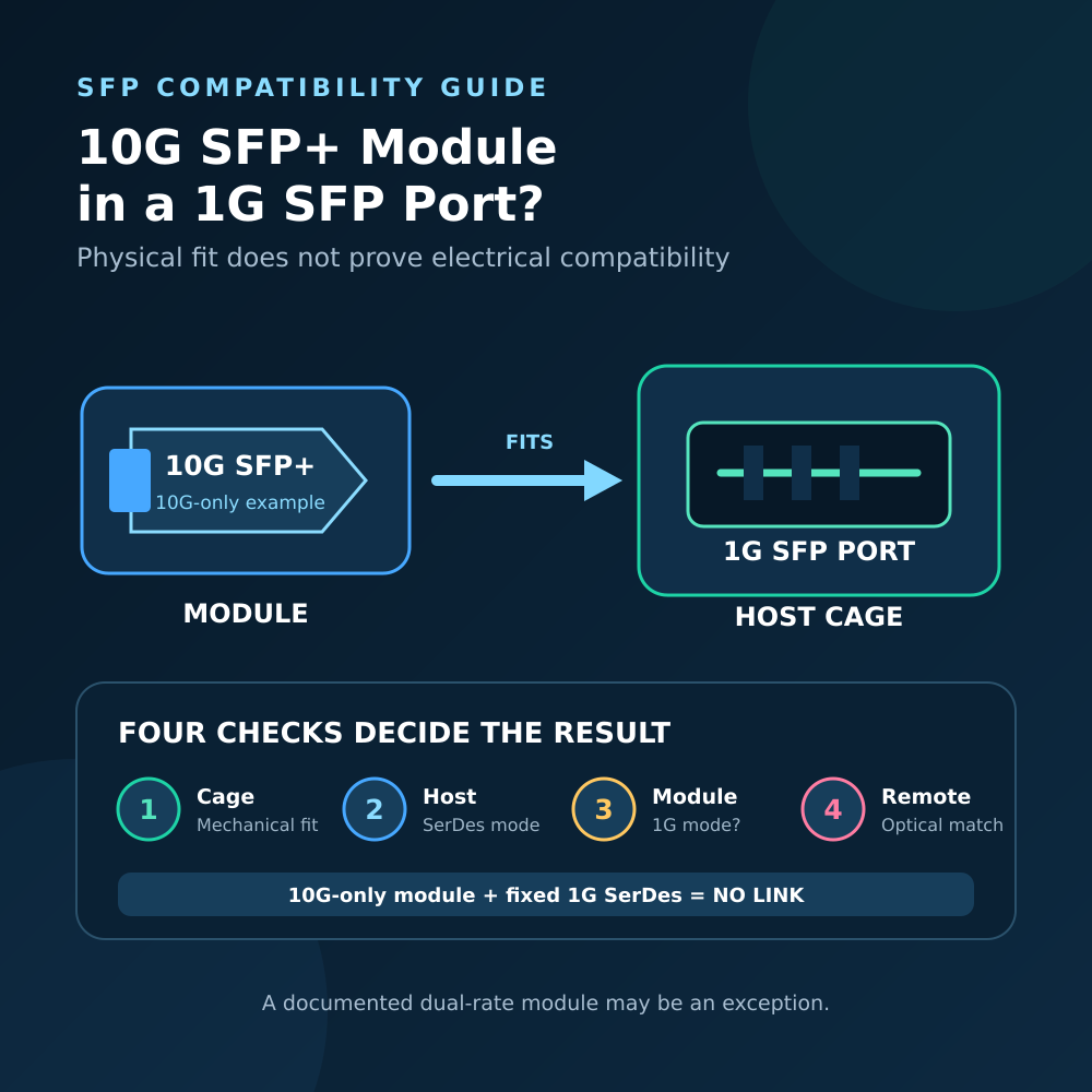
- Host model, port number and supported electrical/SerDes modes
- Module part number, revision, coding and optical PMD
- Actual configured or negotiated rate
- Fiber category, connector and polish
- Any required FEC, auto-negotiation or port-mode setting
An SFP, SFP+ or SFP28 label does not settle these questions. Physical fit, host support, operating mode, link rate and usable traffic performance are separate facts.
Do not use a normal passive loopback for a BiDi test
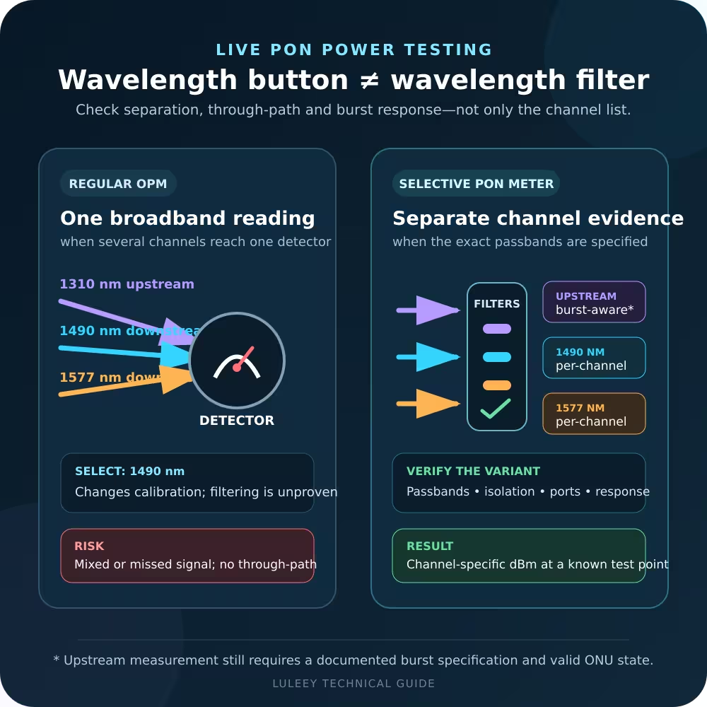
A common single-fiber BiDi pair uses complementary transmit and receive wavelengths. One module may transmit at one wavelength while expecting a different wavelength at its receiver. A passive fiber loop only returns the transmitted wavelength; it does not convert it.
Therefore, no link may be the expected result even when the BiDi module is healthy. Use its correctly matched peer or a wavelength-aware test setup.
2. Check Receiver Power Before Making a Short Loop
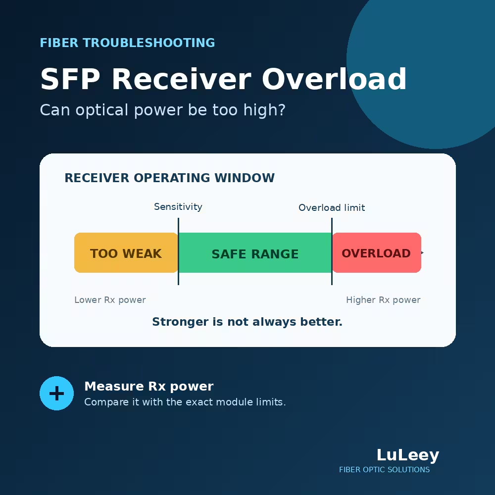
This is the most important safety check for long-reach optics. A production link may include kilometers of fiber and several decibels of loss. A short loopback removes most of that loss and can return too much power to the receiver.
Use the exact module data sheet and calculate the strongest expected receive level:
maximum TX power − minimum loopback-path loss = maximum expected RX power
The result must not exceed the receiver’s maximum operating input for that mode. Include the tolerances of any connector, loopback and attenuator. Do not substitute a damage threshold for the maximum operating input; they answer different questions.
If the data sheet does not publish the upper receiver limit, stop and request it. If attenuation is required, use a correctly specified attenuated loopback or optical attenuator. Do not create loss by tightly bending a patch cord.
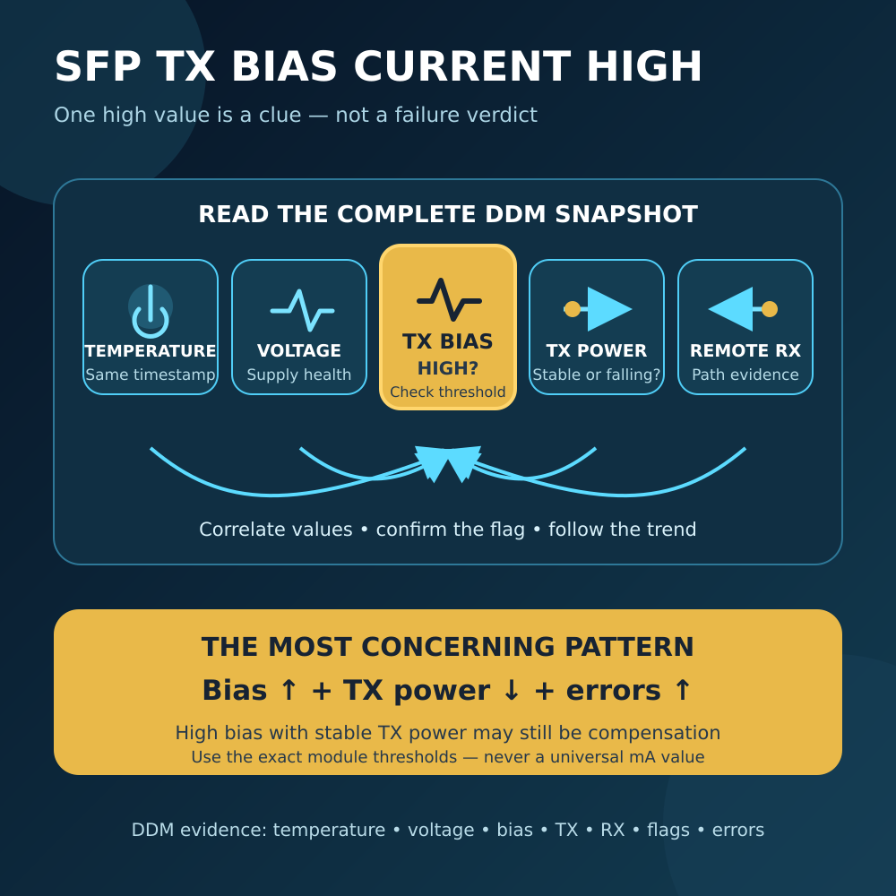
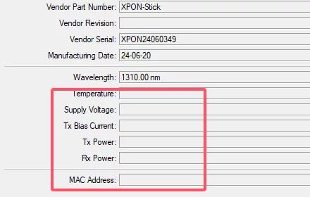
After connection, DDM can provide a useful cross-check where both the module and host expose it. SFF-8472 defines fields for temperature, supply voltage, TX bias, TX power and RX power, and it distinguishes average received power from OMA reporting. DDM accuracy and thresholds still depend on the module; compare the reading with the exact operating limits.
LuLeey’s DDM/DOM field guide explains the five common values, while the receiver-overload guide covers the upper-limit check in more detail.
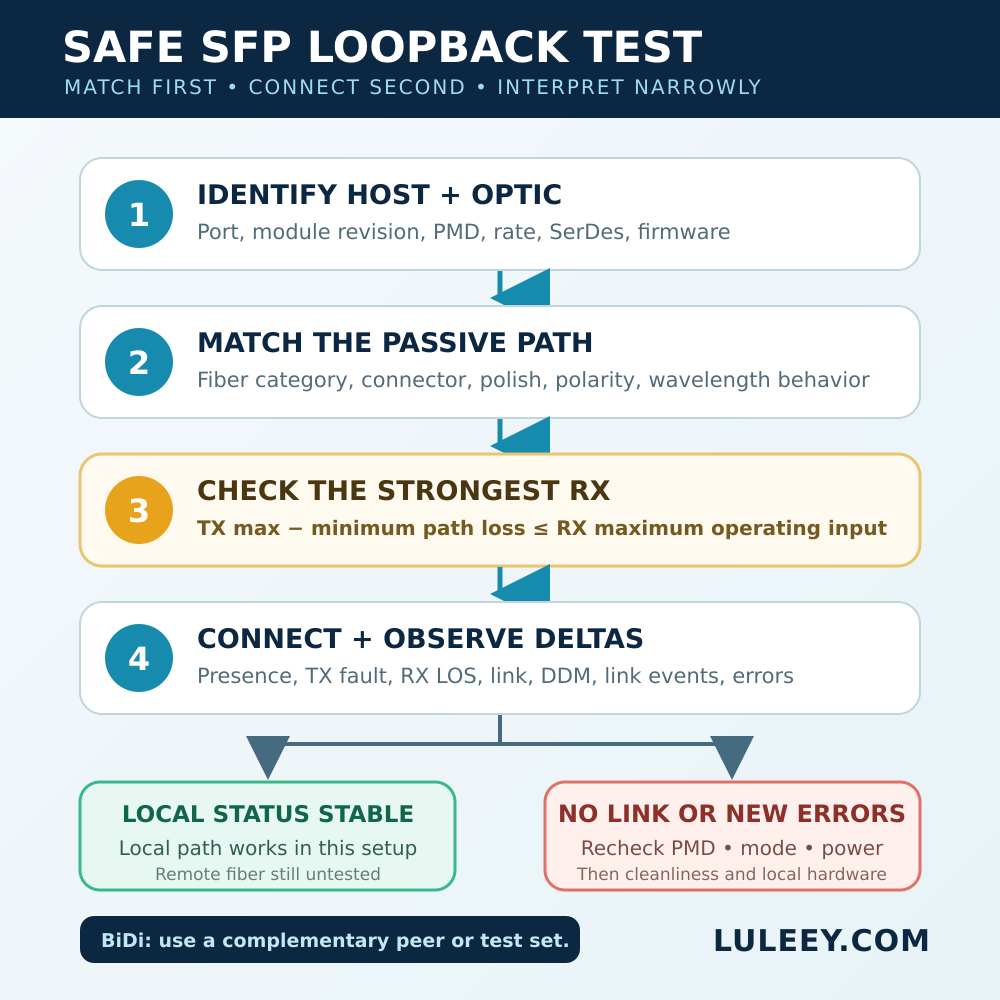
3. Run the Local Loopback Test
Use an approved maintenance window. Disconnecting a production path interrupts service.
- Record the baseline. Save the host model, port configuration, module identity, firmware/driver, current Link/LOS state, DDM readings and error counters.
- Verify the planned combination. Confirm PMD, rate, fiber category, connector/polish and safe receive level. Do not proceed from connector fit alone.
- Inspect and clean. Inspect the loopback and transceiver interface with approved equipment, and clean when required. The Fiber Optic Association connector guide explains how contamination can transfer between mated ferrules. Never look into a fiber or optical port; use an appropriate power meter and video inspection method.
- Insert the correct loopback. Connect local TX to local RX without forcing or twisting the connector. Enable the intended port mode according to the host procedure.
- Observe status and deltas. Check module presence, TX fault, RX LOS, link/PCS state, DDM RX power, link events and new error-counter changes. Record a timed before-and-after comparison.
- Use traffic only if supported. If the platform offers a documented port diagnostic or traffic test, follow that exact procedure. Do not assume that a ping to the device itself traverses the physical port.
- Remove and restore. Disable or isolate the port as required, remove the loopback, protect and clean the interfaces, restore the approved configuration, and confirm normal service.
4. Interpret the Result Without Overclaiming
| Observation | What it supports | Useful next check |
|---|---|---|
| Module is not detected | The host cannot read or accept the module in the current setup | Check cage, power, coding, supported module list, firmware and port mode |
| Module is detected, but RX LOS remains asserted | The local receiver is not seeing an acceptable signal | Check TX enable/fault, fiber and polish match, loopback seating, wavelength behavior and optical power |
| LOS clears or link comes up with stable counters | The tested local optical path works under those conditions | Move outward to the production patch lead, panels, trunk and remote peer |
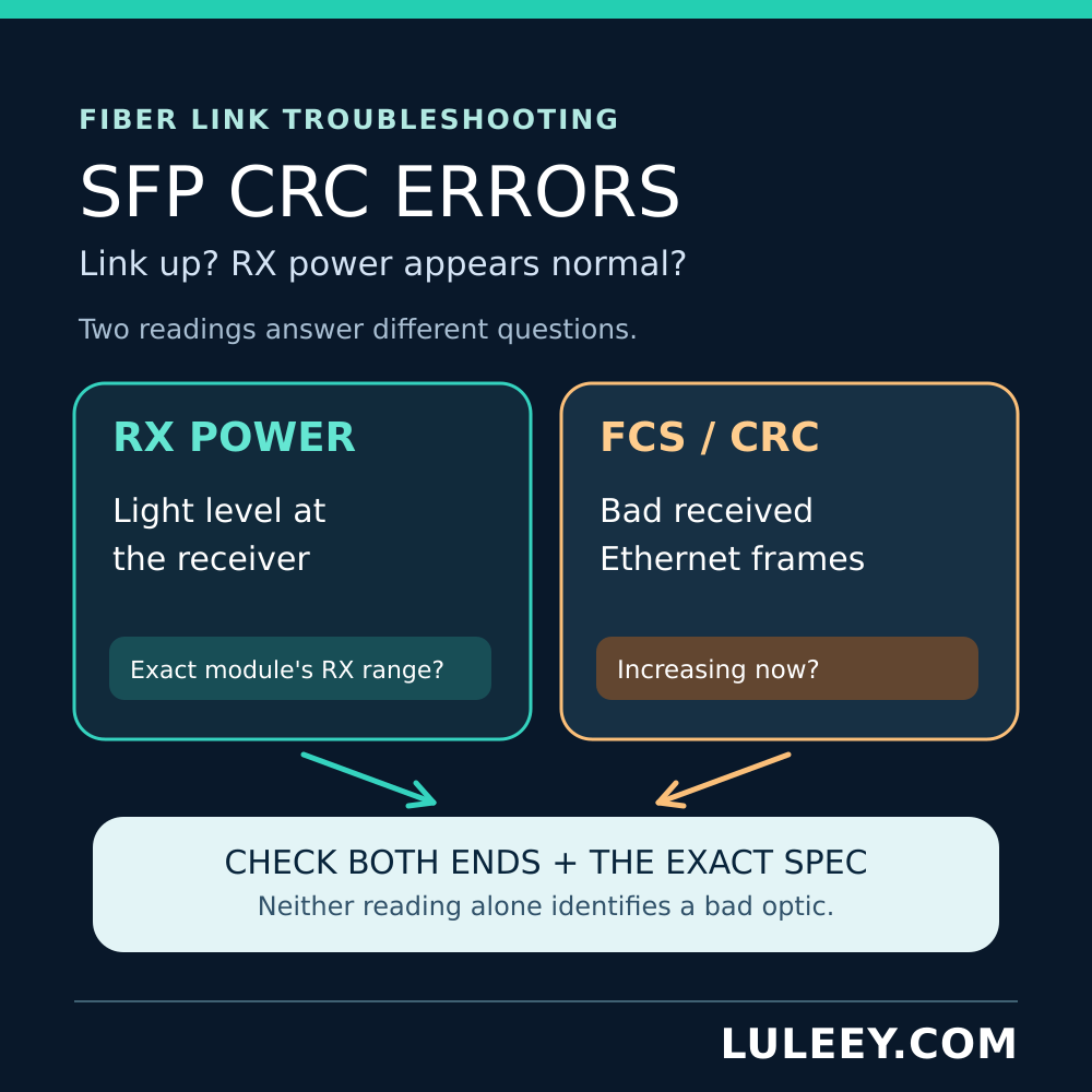
| Link comes up, but errors increase | Signal presence is not clean frame delivery | Check power limits, contamination, PMD/rate/FEC settings and the local module/host path |
| A BiDi module does not link to itself | This may be normal because TX and RX wavelengths differ | Use the complementary BiDi peer or a wavelength-aware setup |
A successful local loop narrows the fault domain. It does not certify temperature margin, long-term error performance or compatibility with the remote device. Conversely, a failed loop is not immediate proof of a bad module: the test setup, host behavior, port configuration or excessive/insufficient optical power can be responsible.
If the interface links but errors rise, continue with LuLeey’s SFP CRC troubleshooting guide and compare fresh counter deltas rather than a historic total.
Choosing a LuLeey Loopback
LuLeey’s LC/UPC OM3 multimode fiber loopback is listed as 50/125 µm multimode with an LC/UPC interface and insertion loss of no more than 0.2 dB. Those facts do not make it universal.
The published value is a maximum insertion loss, not a guaranteed minimum attenuation. It cannot by itself prove that a short loop is safe for an unknown transmitter/receiver pair. The page also uses broad rate wording; select the loopback from the exact PMD, lane arrangement, module limits and host behavior rather than from an SFP-family name or nominal rate alone.
Next step: send LuLeey the host model and port, module part number/revision, optical PMD, fiber/connector type, configured rate, firmware and the module’s TX/RX operating limits. LuLeey can then confirm the appropriate loopback type and whether controlled attenuation is required.
 SFP/SFP+ (1G/2.5G/5G/10G)
 SFP-T (1G/2.5G/10G)
 AOC Cable 10G/25G/40G/100G
 DAC Cable 10G/25G/40G/100G
 QSFP28 QSFP+ SFP28 100G/40G/25G
 Copper to Fiber Media Converters
 Fiber Media Converter PCBA Board
 OEO Fiber Media Converters
 Serial to Fiber Media Converters
 Video to Fiber Media Converters
 1000M GPON/EPON ONU
 10G EPON ONU/XG-PON/XGS-PON
 2.5G GPON/XPON STICK SFP ONU
 POE GPON/EPON ONU
 Wireless GPON/EPON ONT
 EPON OLT
 GPON OLT
 SFP PON Module
 Industrial Switches
 Managed Switches
 POE Switches
 Unmanaged Switches
 MTP/MPO Fiber Cables
 Fiber Optic Cassettes
 Fiber Optic Loopback
 Optic Cables and Fiber Pigtails
 Optical Splitters and Splitter Box
 Fiber Flange Connectors
 Optical Adapters
 Optical Attenuator
 Quick Connector and Connector Panel
 CATV Amplifier
 CATV Optical Receiver
 Visual Fault Locator
 OTDR
OTDR Optical Power Meter
 Fiber Optic Identifier
 Fiber Optic Cleaners
 Fiber Cleavers & Fiber Strippers
 Copper Tools


