Customs duties are the responsibility of customers, but standard logistics support DDP to most countries, duty-free such as US, DE, UK, CA, FR, IT, PL, AT, JP…





















































Can an SFP work beyond the rated distance? Sometimes, yes. A 10 km optic may establish a link over a route slightly longer than 10 km when the transmitter, receiver and cable plant are favorable. But that result is not guaranteed, and a link-up LED does not prove that the connection has enough margin for temperature changes, component aging or future repairs.
The safe approach is to treat the distance label as an application rating—not a timer that stops the signal at exactly 10,000 meters. Verify the exact optical specifications, calculate both the weak-signal and strong-signal cases, account for dispersion and other path penalties, and then test both directions for errors.
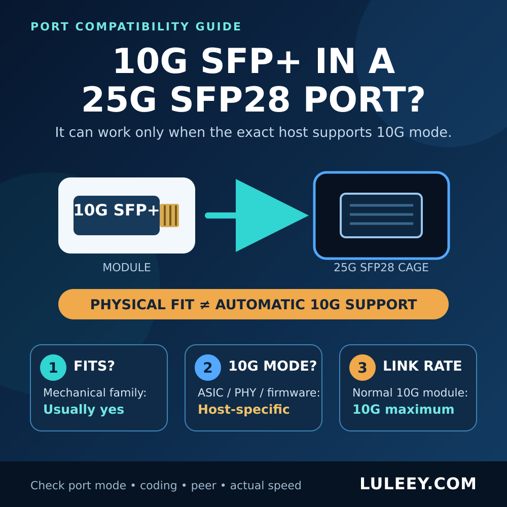
Scope: This guide covers point-to-point optical Ethernet links using SFP-family transceivers. It is not an automatic compatibility verdict for a 2.5G PON ONU stick. For an ONU stick, verify the exact host cage, SerDes or PHY mode, firmware or driver, port setting, module coding, stick host mode, actual negotiated rate and resulting throughput.

Can an SFP Work Beyond the Rated Distance? The Short Answer
| Situation | What it means | Recommended decision |
|---|---|---|
| A link comes up slightly beyond the rating | The installed pair and path may have favorable headroom | Treat it as an engineered exception until worst-case limits and traffic tests pass |
| Received power is above sensitivity but errors rise | Average power is not the only limit | Check dispersion, reflections, signal quality, FEC and host compatibility |
| A long-reach optic is used on a short, low-loss link | The receiver may get too much power | Check maximum TX power, minimum path loss and Receiver Overload |
| One direction passes and the other fails | The two transmitters, receivers or paths differ | Calculate and test A→B and B→A separately |
| The only evidence is a green link LED | Basic synchronization occurred at that moment | Do not claim reliable extended reach without margin and error testing |
What the Rated Distance Actually Means
A reach label such as 550 m, 10 km, 20 km or 40 km normally summarizes the application the optic was designed to support under specified conditions. Those conditions can include:
- protocol and physical-medium specification;
- line rate, coding and FEC mode;
- fiber type and operating wavelength;
- transmitter output range;
- Receiver Sensitivity and maximum input;
- allowable channel loss and optical path penalty;
- dispersion and return-loss constraints;
- connector, splice and patch-cord assumptions;
- temperature and manufacturing tolerances.
Distance is convenient for selection, but it is not the only engineering limit. An IEEE 802.3 working-group contribution titled What’s so special about 10km? makes the same broad point: round-number reaches should not be treated as having “mystical” physical properties, and optical breakpoints are closely related to technology and loss budgets. That presentation is a working-group contribution rather than the IEEE standard itself, so use it as engineering context—not as a universal compliance rule.
Why can one pair work past the label? The actual transmitter may launch more than its specified minimum, the actual receiver may perform better than its guaranteed limit, and the installed fiber may lose less than the maximum design assumption. All three can create sample-specific headroom.
The problem is that a production design must survive the opposite case: a transmitter near its minimum output, a receiver near its guaranteed requirement, maximum permitted channel loss, temperature extremes, aging and measurement uncertainty. A favorable bench result does not replace those worst-case checks.
Power Budget for an SFP Beyond the Rated Distance
The first calculation is the low-power case. For one direction:
Worst-case RX power (dBm) = minimum TX power (dBm) − maximum path loss (dB)
The result must meet the exact receiver requirement with the engineering margin required by the project:
Remaining margin (dB) = worst-case RX power − receiver requirement
Because dBm values can be negative, a less-negative result is stronger. For example, −12 dBm is 2 dB stronger than −14 dBm.
The second calculation is the high-power case:
Strongest RX power (dBm) = maximum TX power (dBm) − minimum path loss (dB)
That result must not be stronger than the receiver’s maximum operating input or overload limit. Do not confuse an overload limit with a damage threshold; normal operation may become unreliable well before permanent damage is possible.
A simple illustrative example
Assume an exact module data sheet gives these values for a particular operating mode:
- minimum TX power: −5 dBm;
- maximum TX power: 0 dBm;
- receiver requirement: −14 dBm;
- receiver overload: −3 dBm.
If the route can lose as much as 7 dB:
−5 dBm − 7 dB = −12 dBm
That is 2 dB above a −14 dBm receiver requirement. If the project requires 2 dB of engineering margin, there is no spare margin left.
If the same optic is tested over a path that loses only 1 dB:
0 dBm − 1 dB = −1 dBm
That is 2 dB stronger than a −3 dBm overload limit, so the short path would be outside the stated operating window.
These figures are examples only. Use the exact minimum and maximum values for both installed part numbers.
The cable-plant loss should include fiber attenuation at the operating wavelength, mated connections, splices, patch cords, splitters, filters, muxes and any intentional attenuator. LuLeey’s dB vs dBm guide explains why passive loss in dB is subtracted from optical power in dBm.
The Fiber Optic Association also warns that power budget and cable-plant loss budget are related but not identical. Dispersion, receiver noise and other impairments can reduce usable performance even when the simple arithmetic appears to pass. Use conservative component values and a margin appropriate to the exact application; there is no universal margin number that fits every Ethernet optical interface.
Why Enough RX Power May Still Not Be Enough
Dispersion can close the eye
Chromatic dispersion in long single-mode links and modal dispersion in multimode links spread optical pulses over time. The receiver may report acceptable average power while the ones and zeros become difficult to distinguish.
Use the reach, dispersion tolerance and optical-path-penalty conditions defined for the exact interface. Do not extend a link solely because a power-budget spreadsheet has a positive result. Also check whether a published channel-loss allowance already includes specified penalties so the same penalty is not subtracted twice.
Reflectance can disturb the transmitter or receiver
Dirty, damaged or poorly matched connectors can create reflections as well as insertion loss. Average RX power may look plausible while return loss or intermittent movement causes errors. Inspect, clean and re-inspect every accessible connection.
Link-up is not the same as error-free service
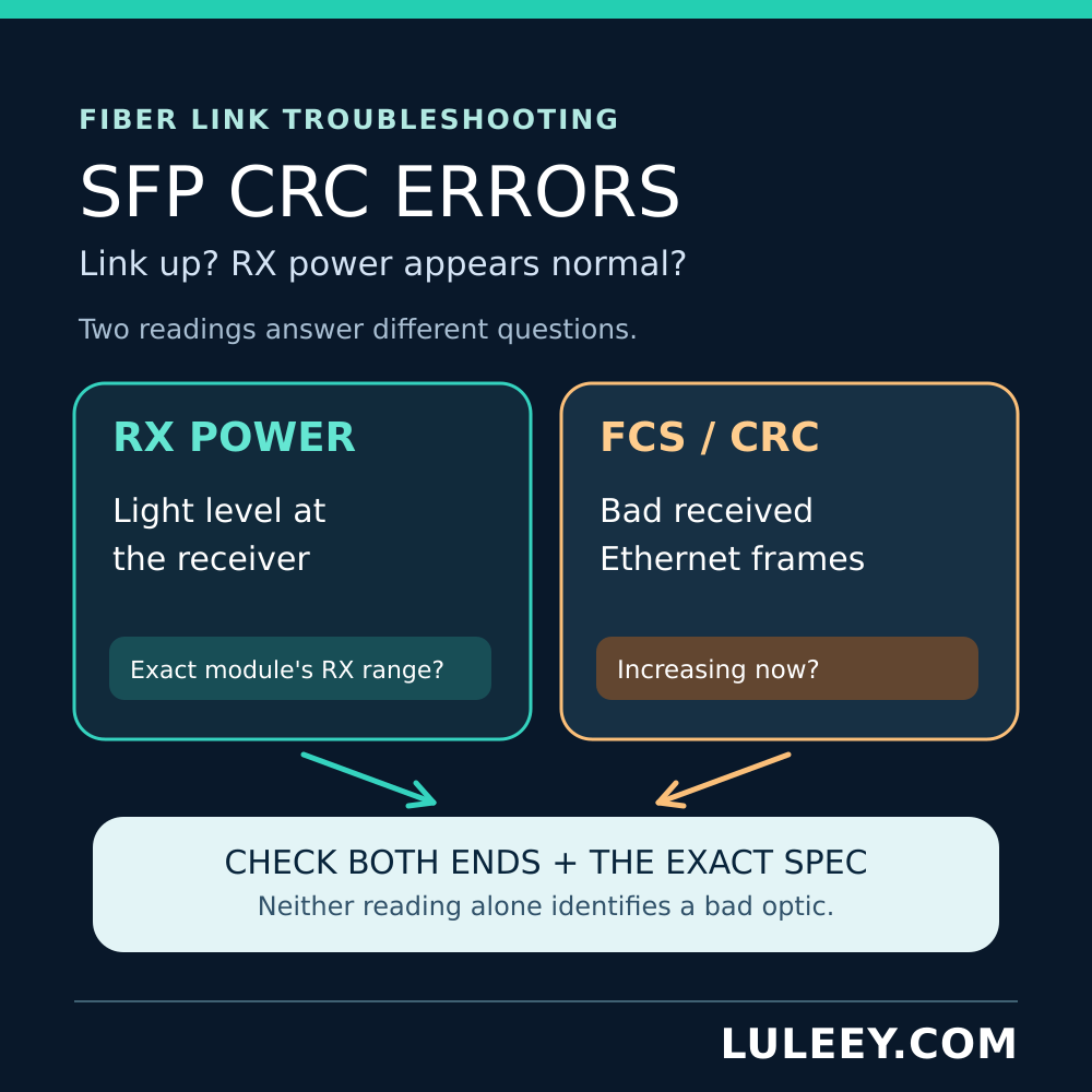
A green LED shows that the endpoints synchronized at that moment. It does not show the bit-error rate, corrected FEC workload, uncorrectable errors, CRC or PCS errors, link flaps, or performance at temperature extremes.
For a link operated beyond its rating, test representative traffic and record error counters before and after the test. If FEC is active, monitor corrected and uncorrectable codewords where available.
Host and module compatibility still applies
An optical budget cannot fix an electrical or protocol mismatch. Confirm the host port’s supported SerDes mode, line rate, encoding, FEC behavior, module coding, firmware support and power or thermal limits. The words SFP, SFP+, SFP28 and a headline data rate describe only part of the interface.
How to Verify a Link Beyond the Rated Distance
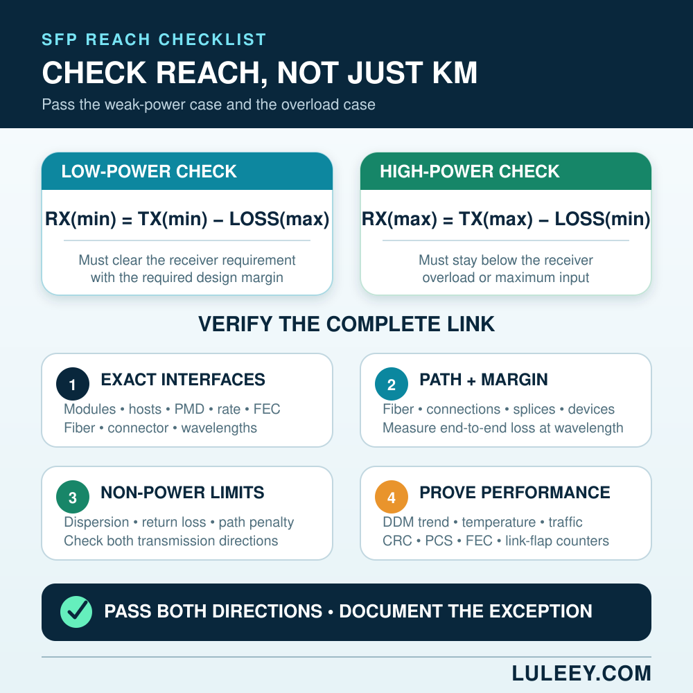
1. Identify both endpoints exactly
Record host models, ports, firmware or driver versions, transceiver manufacturers, complete part numbers and hardware revisions.
2. Confirm the optical application
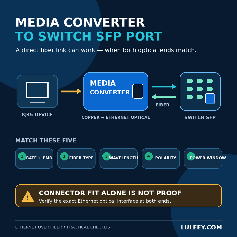
Verify the protocol or PMD, operating rate, encoding, FEC, connector, fiber type and wavelength. BiDi modules require complementary transmit and receive wavelengths.
3. Collect worst-case specifications
For each direction, obtain:
- minimum and maximum TX power;
- receiver performance requirement;
- overload or maximum operating input;
- minimum channel loss, if stated;
- allowable channel loss;
- dispersion or reach condition;
- operating-temperature range.
Do not substitute DDM alarm thresholds for guaranteed optical-interface specifications.
4. Map and measure the complete path
Document route length, fiber type, connections, splices, patch panels, passive devices and patch cords. Calculate a conservative budget, then measure insertion loss at the relevant wavelength when defensible evidence is required.
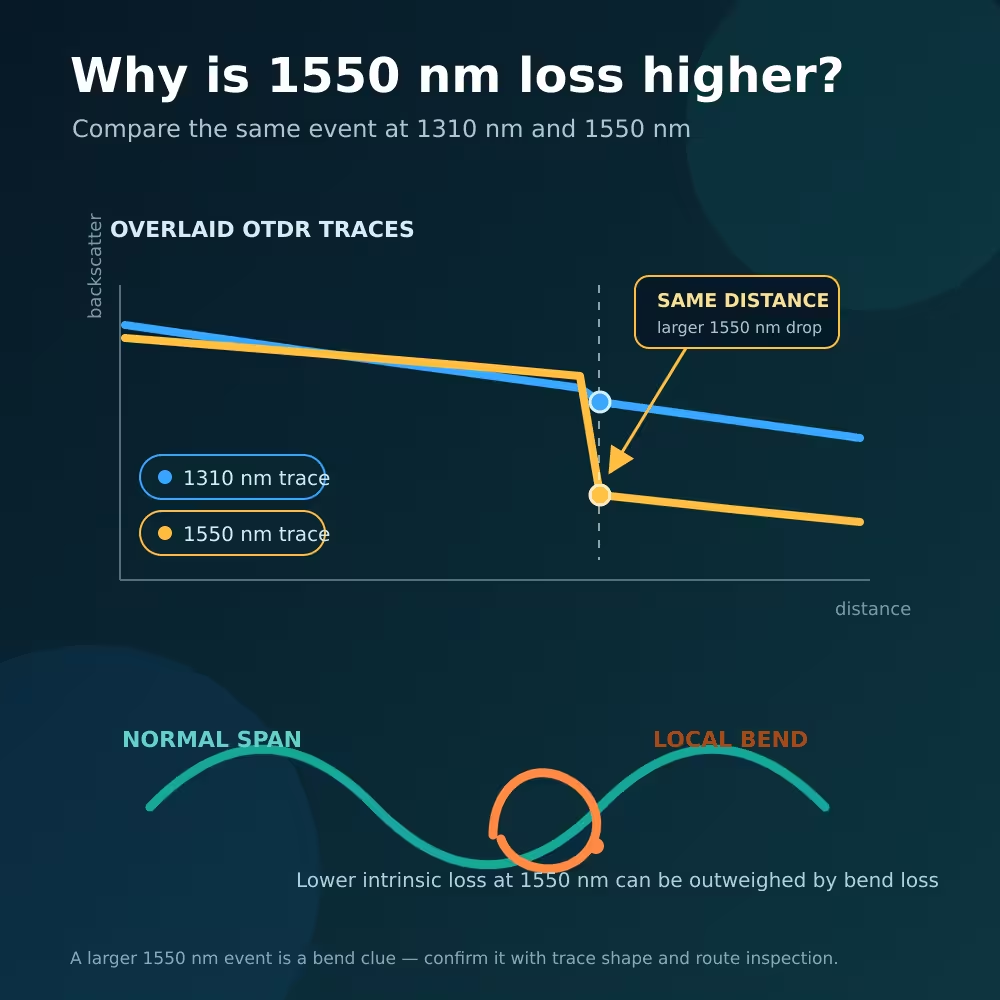
An OTDR can locate events and measure length, but it is not automatically a substitute for an end-to-end insertion-loss test.
5. Check both weak and strong power cases
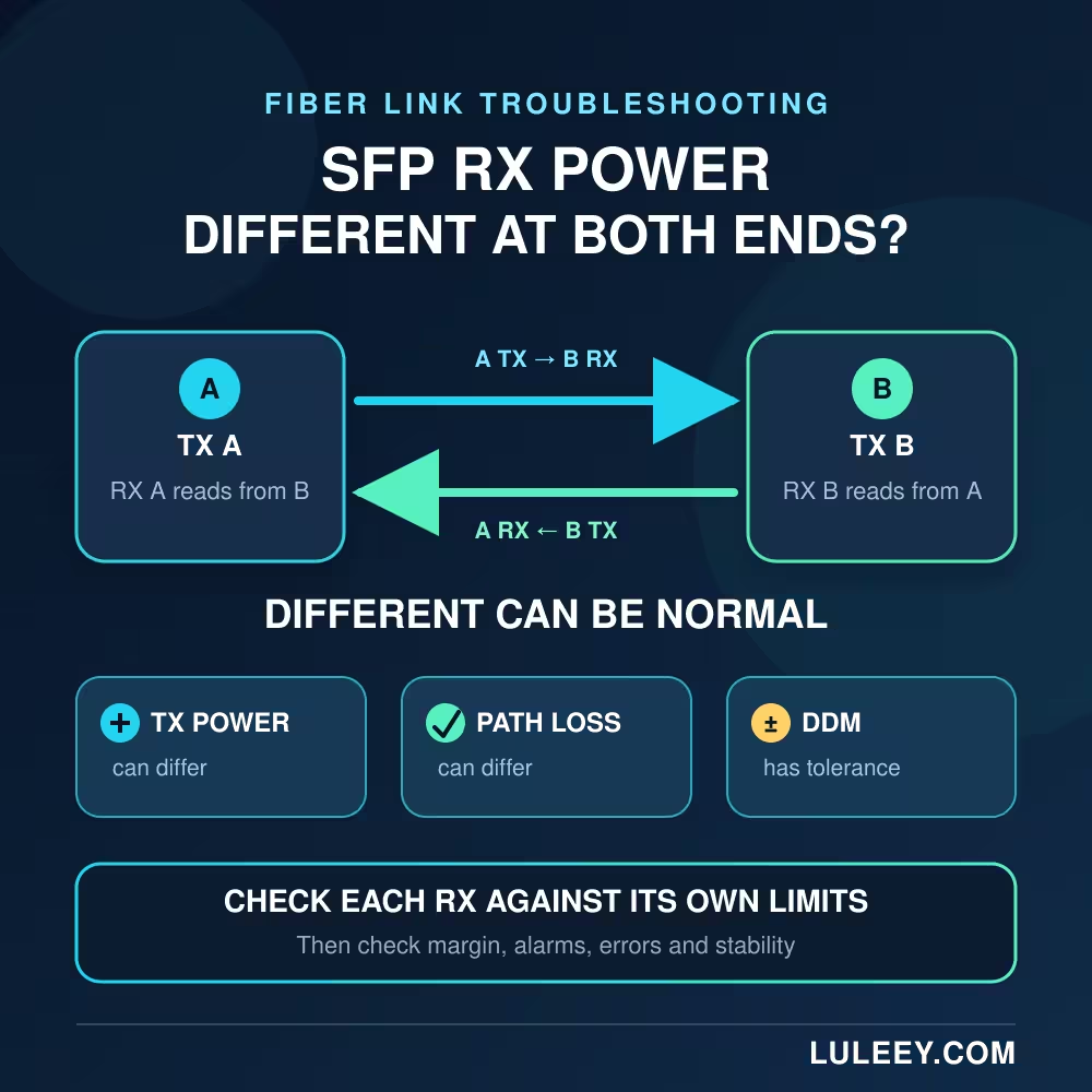
Calculate A→B and B→A separately. Use minimum TX with maximum path loss for the weak case, and maximum TX with minimum path loss for the overload case.
6. Check non-power limits
Verify dispersion, return loss, optical path penalty, FEC and any vendor-specific reach conditions. If these are unknown, do not infer extended-distance reliability from RX dBm alone.
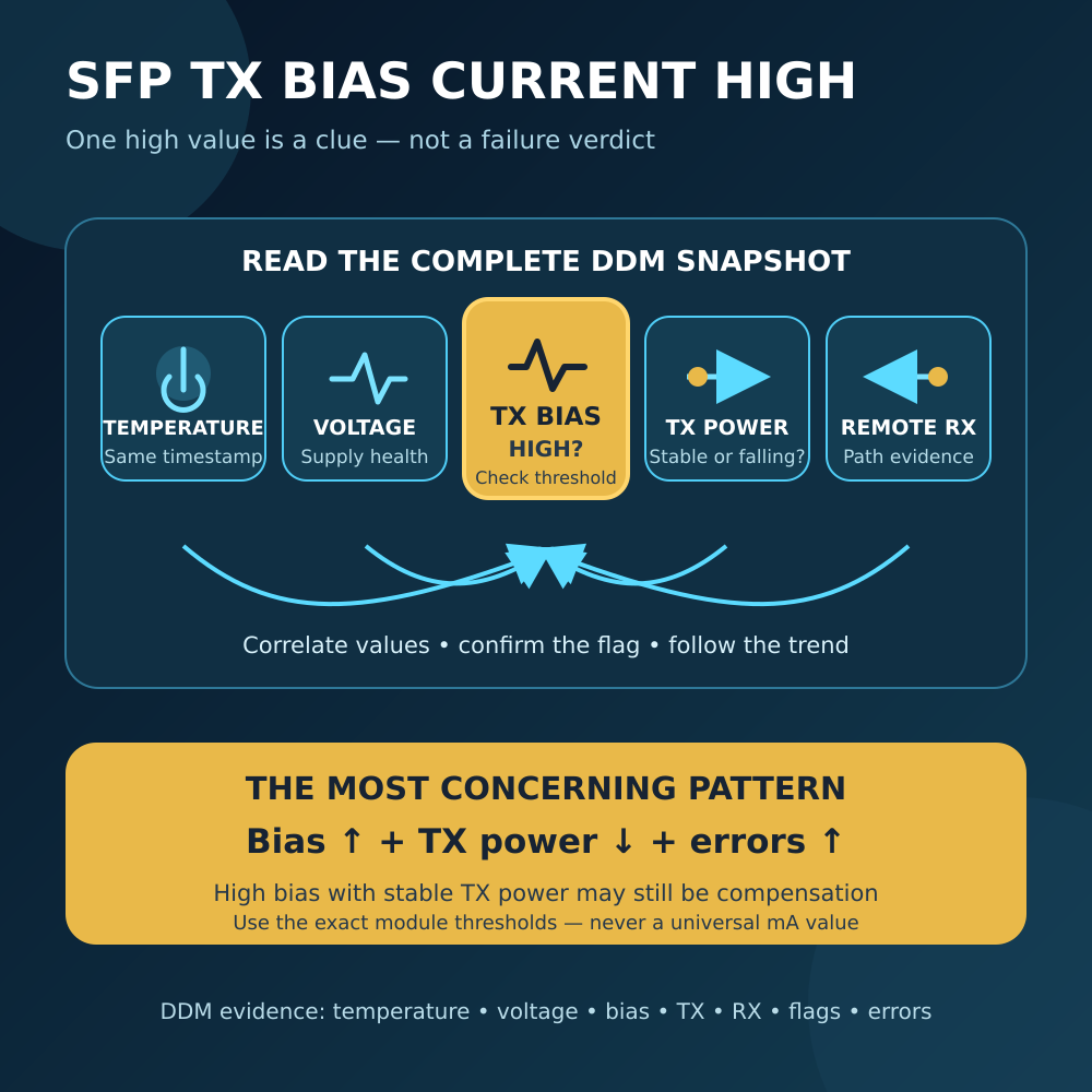
7. Use DDM as telemetry, not final certification
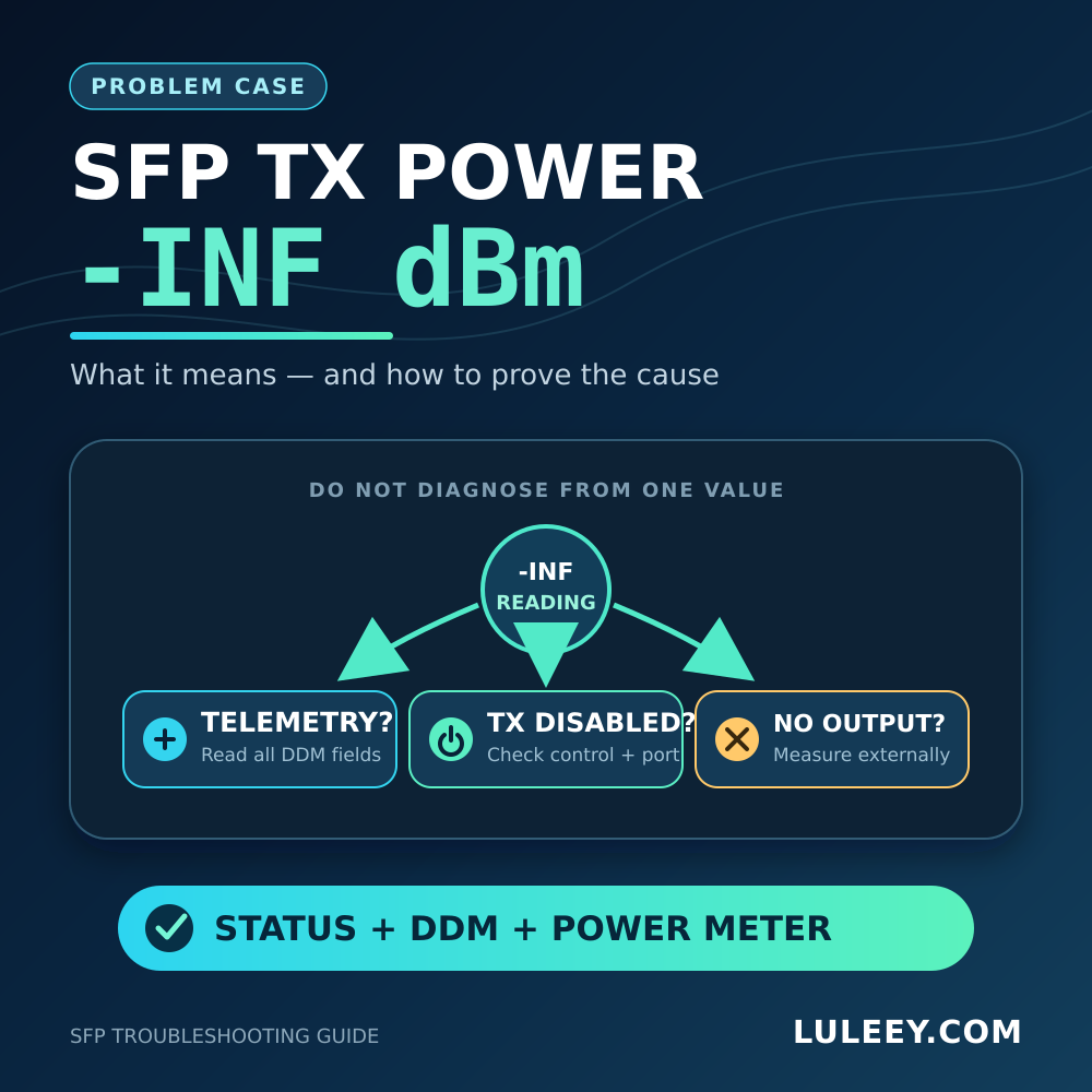
Capture TX power, RX power, temperature, voltage, bias current and alarms at both ends. The current SNIA SFF-8472 specification says that absolute TX and RX diagnostic accuracy must be better than ±3 dB over the required range and specified conditions.
Actual implementations may be better, but a display with two decimal places is not automatically a precision loss test. LuLeey’s DDM/DOM guide explains the diagnostic fields.
8. Test traffic, errors and temperature
Run representative bidirectional traffic and observe CRC/FCS, symbol, PCS, FEC and link-flap counters. Repeat the check under realistic operating temperatures.
9. Document the exception
If the route exceeds the rating but passes the engineered checks, record the exact module pair, path loss, margin, test conditions and acceptance criteria. Do not relabel the module or promise the same result for another production lot or cable path.
Can You Use a Long-Reach SFP on a Short Link?
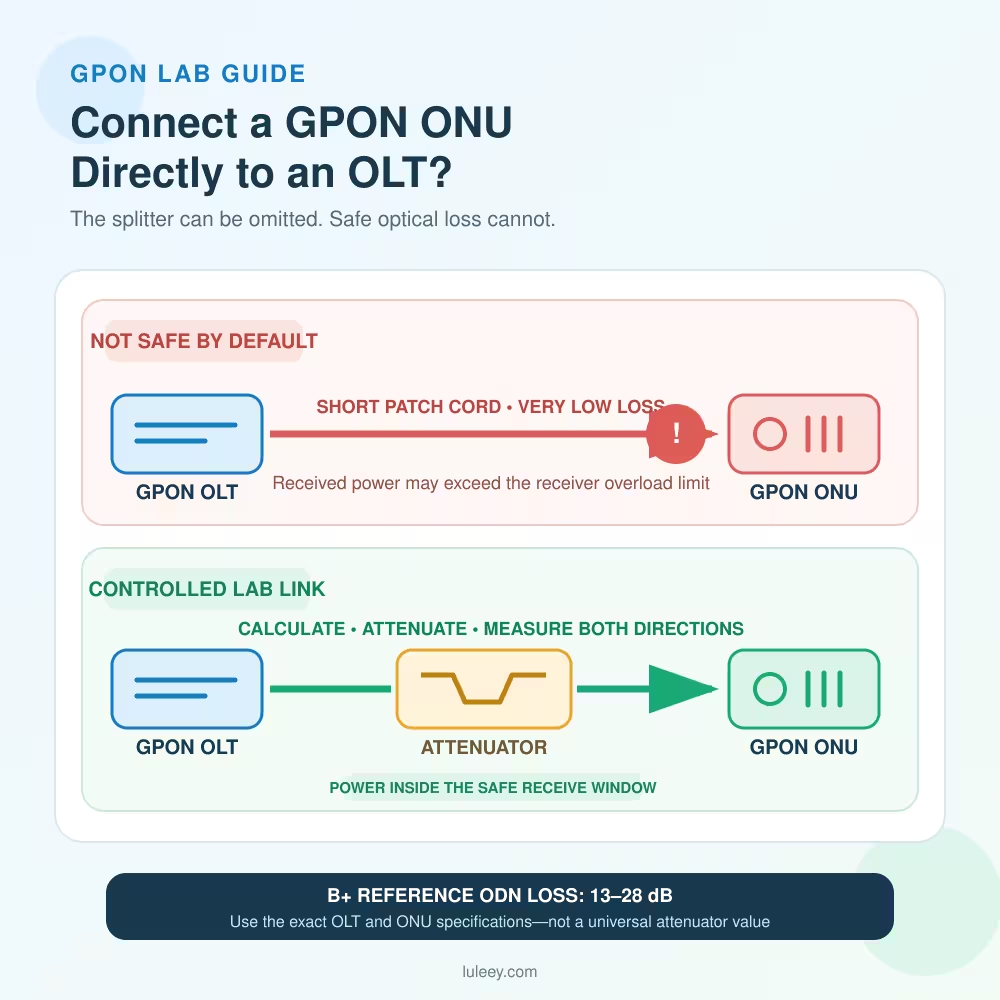
Sometimes, but do not decide from the distance label alone. The high-power calculation must keep the receiver below its overload limit and satisfy any stated minimum channel loss.
Do not add an attenuator automatically. First compare maximum TX power, minimum path loss and receiver overload. If attenuation is required, select a wavelength- and connector-compatible value, then remeasure.
On a dual-fiber link, an attenuator can be applied to the affected receive direction. On a BiDi link, an inline attenuator affects both wavelengths and both directions. LuLeey’s SFP receiver-overload guide covers this decision in more detail.
Can You Mix Different Reach Ratings at the Two Ends?
It may work only when the exact interfaces are interoperable and both directional budgets overlap. Check:
- protocol, rate and PMD;
- encoding and FEC expectations;
- fiber and connector types;
- transmit and receive wavelengths;
- low-power margin in both directions;
- overload in both directions;
- explicit host support.
For BiDi, the transmit wavelength at one end must match the receive wavelength at the other. A 10 km module and a 20 km module are not proven compatible merely because both fit an SFP cage.
A Practical Pass/Fail Rule
| Result | Decision |
|---|---|
| Within rated reach; all specifications and tests pass | Standard deployment |
| Slightly beyond reach; both budgets, penalties, margin and error tests pass | Possible engineered exception; not a general product guarantee |
| RX looks good but errors, FEC corrections or flaps rise | Fail until the cause is resolved |
| Weak-case margin is inadequate | Use a supported higher-budget solution, reduce loss or regenerate the link |
| Strong-case power exceeds overload | Add calculated loss or choose an appropriate optic; then retest |
| Required dispersion or interoperability data is missing | Do not approve extended reach from link-up alone |
Practical Next Step
Build a two-direction worksheet containing the exact host and module part numbers, operating mode, wavelength, route length, measured insertion loss, minimum and maximum TX power, receiver requirement, overload limit, chosen margin, DDM snapshot and traffic-error results.


 SFP/SFP+ (1G/2.5G/5G/10G)
 SFP-T (1G/2.5G/10G)
 AOC Cable 10G/25G/40G/100G
 DAC Cable 10G/25G/40G/100G
 QSFP28 QSFP+ SFP28 100G/40G/25G
 Copper to Fiber Media Converters
 Fiber Media Converter PCBA Board
 OEO Fiber Media Converters
 Serial to Fiber Media Converters
 Video to Fiber Media Converters
 1000M GPON/EPON ONU
 10G EPON ONU/XG-PON/XGS-PON
 2.5G GPON/XPON STICK SFP ONU
 POE GPON/EPON ONU
 Wireless GPON/EPON ONT
 EPON OLT
 GPON OLT
 SFP PON Module
 Industrial Switches
 Managed Switches
 POE Switches
 Unmanaged Switches
 MTP/MPO Fiber Cables
 Fiber Optic Cassettes
 Fiber Optic Loopback
 Optic Cables and Fiber Pigtails
 Optical Splitters and Splitter Box
 Fiber Flange Connectors
 Optical Adapters
 Optical Attenuator
 Quick Connector and Connector Panel
 CATV Amplifier
 CATV Optical Receiver
 Visual Fault Locator
 OTDR
OTDR Optical Power Meter
 Fiber Optic Identifier
 Fiber Optic Cleaners
 Fiber Cleavers & Fiber Strippers
 Copper Tools


