Customs duties are the responsibility of customers, but standard logistics support DDP to most countries, duty-free such as US, DE, UK, CA, FR, IT, PL, AT, JP…





















































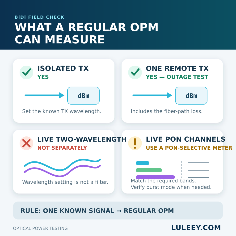
A BiDi SFP optical power test can be done with a regular optical power meter when the meter receives one known transmitter wavelength at a time. The same meter normally cannot separate two live wavelengths on a working single-fiber link, and changing its wavelength setting does not add a wavelength filter.
That distinction prevents two common mistakes: trusting a combined live reading as if it belonged to one direction, and rejecting a healthy module because the meter was set to the wrong calibration wavelength.

BiDi SFP Optical Power Test: What a Regular Meter Can Do
| Test question | Regular one-port optical power meter? | Important condition |
|---|---|---|
| Measure one module’s transmitter output | Yes | The transmitter is enabled, its wavelength is known, and the meter supports that wavelength and power range |
| Measure power arriving across the fiber from the remote module | Yes | The receiver end is disconnected, so the test interrupts the link |
| Separate both directions on a live single-fiber BiDi link | No, not by itself | Use a wavelength-selective and suitably directional live-test setup |
| Identify an unknown optical wavelength | No | Use a wavelength meter or optical spectrum analyzer |
| Measure separate live PON channels and upstream bursts | No | Use a PON meter that explicitly supports the required bands and burst measurement |
The short rule is simple: one known signal is measurable; simultaneous wavelengths are not individually identified by a normal broadband power meter.
Why BiDi Testing Is Different
A normal duplex optical link uses one fiber for transmit and another for receive. A fixed-wavelength BiDi pair uses one strand in both directions. An internal wavelength-selective component combines the local transmitter with the local receiver:
- Side A transmits at wavelength A and receives wavelength B.
- Side B transmits at wavelength B and receives wavelength A.
This use of wavelength-division components to combine and separate two wavelengths on one strand is documented in the Ethernet Alliance’s Single-Fiber Ethernet material. ethernetalliance.org
The two modules therefore need complementary TX and RX wavelengths. They must also match in application, line rate, reach class, connector, fiber type, optical budget and host support. If pairing is still uncertain, first use LuLeey’s guide to two identical BiDi SFP modules.
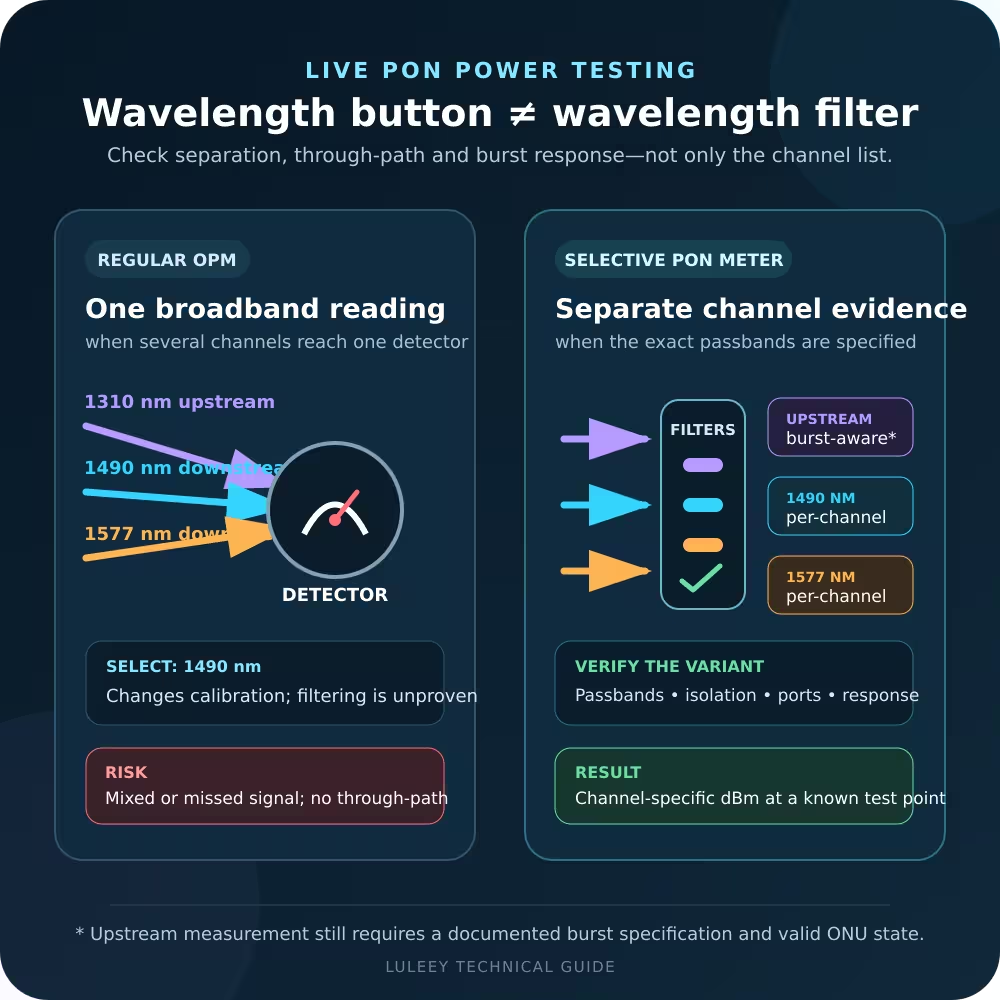
A regular optical power meter has a broadband photodetector. It reports the average optical power reaching that detector. Its wavelength selection applies the calibration for the chosen wavelength because detector response changes with wavelength. It does not tune the meter so that all other wavelengths disappear. Fiber Optic Instruments
This is why selecting 1310 nm cannot isolate a 1310 nm channel from another live wavelength on the same test port. If several wavelengths reach the detector, the display is not a trustworthy per-channel result.
Test 1: Measure the BiDi SFP Transmitter Output
This is the cleanest test because only the local transmitter is connected to the meter.
1. Record the exact module and host conditions
Write down:
- Module manufacturer, part number and revision
- Nominal TX wavelength and allowed wavelength range
- Published minimum and maximum TX power
- Host model, port, firmware or driver, and configured line rate
- Connector type and polish
- Whether the transmitter is enabled
Do not work from the words “SFP,” “SFP+,” or “BiDi” alone. Physical fit does not prove the correct host SerDes mode, actual link rate, coding or optical specification.
2. Check the meter before connecting it
Confirm that the optical power meter:
- Has a calibration point or documented accuracy for the module’s TX wavelength
- Covers the full expected power range without overload
- Uses the correct adapter and connector polish
- Has a valid calibration status for the accuracy you need
For example, if a module transmits near 1270 nm or 1330 nm, do not assume a meter calibrated only at 1310 nm will meet your required uncertainty. The meter manufacturer must state how that wavelength is handled.
3. Inspect and clean the test path
Use a known-good reference jumper that matches the module’s fiber and connector. Follow an inspect-clean-inspect process. A dirty connector can add loss and can contaminate the meter adapter.
Never look into a module, connector or fiber. Treat it as active until verified with the correct procedure.
4. Isolate one transmitter
Keep the BiDi module installed in its supported host and ensure the transmitter is enabled. Connect its optical port to the power meter through the reference jumper.
The remote BiDi module is not part of this setup. The meter now receives only the local TX wavelength.
5. Set the wavelength and read power in dBm
Select the module’s TX wavelength or the instrument setting explicitly approved for it. Use dBm for absolute optical power, allow the reading to settle, and record the operating state.
Traffic pattern and transmitter state can affect the exact average-power result. For a field check, record whether the port was linked, forced on, in a test mode or simply transmitting without a peer. For a compliance measurement, follow the module or standard’s specified test pattern and conditions.
6. Compare with the exact data sheet
Compare the result with the minimum and maximum TX power for that exact part number and operating mode. Do not use a generic limit from another BiDi module with the same distance label.
A reading inside the TX range supports that the module is launching plausible power under the test conditions. It does not prove the wavelength is correct, the signal quality is good, the host accepts the module, or the remote receiver can recover traffic.
Test 2: Measure Power Arriving Across the Fiber
This test checks the remote transmitter plus the installed optical path.
- Arrange a maintenance window because the local receiver must be disconnected.
- Keep the remote BiDi module installed and confirm that its TX remains enabled without an active peer.
- Disconnect the local module from the fiber and connect the fiber to the meter.
- Set the meter to the remote module’s TX wavelength.
- Record the received power in dBm.
- Compare it with the local module’s specified receiver operating range, including both the low-power limit and the maximum allowed input.
The reading includes losses from the route, connectors, splices and any passive components. It is not the remote module’s bare transmitter output.
Some hosts disable a laser when the port is shut down or when a diagnostic condition occurs. If the meter shows no power, confirm TX enable and TX-fault status before blaming the fiber.
Why a Regular Meter Cannot Separate a Live BiDi Link
A one-port power meter terminates the fiber; it does not normally pass traffic through. Connecting it in place of a BiDi module therefore takes that end of the link offline.
Adding a passive tap can keep endpoints connected, but it creates a different measurement problem. If the sampled port contains both BiDi wavelengths, a regular broadband detector cannot tell how much power belongs to each one. The displayed number depends on the combined optical energy and the detector’s wavelength response, while the selected calibration applies to only one wavelength.
For non-disruptive, per-wavelength measurements, use a setup designed for the task, such as:
- A wavelength-selective power meter with the required bands
- An optical spectrum analyzer with suitable power accuracy and resolution
- A purpose-built directional optical tap or monitor that preserves direction and accounts for tap loss
Check the live setup’s insertion loss before placing it in a marginal link. A tap or monitor changes the optical budget.
DDM vs an External Power Meter
Digital diagnostic monitoring can report TX power and RX power from the installed module. It is valuable because it observes the link without disconnecting the fiber. LuLeey’s DDM/DOM guide explains the common readings.
SNIA SFF-8472 defines TX output-power and RX input-power diagnostic fields, but it also makes their accuracy dependent on wavelength, operating conditions and vendor implementation. members.snia.org
DDM and an external meter do not measure at the same point:
| Reading | Measurement point | Best use |
|---|---|---|
| Module TX DDM | Internal transmitter monitor | Trend the module’s launch behavior and alarms |
| External meter at module output | After the module connector and reference jumper | Independent field check of delivered optical power |
| Module RX DDM | Inside the installed receiver | Observe the live received level and changes over time |
| External meter at receiver-end fiber | At the disconnected fiber end | Check arriving power with a separate instrument |
Small differences can come from connector loss, test-jumper loss, wavelength response, calibration, averaging and module accuracy. A large difference should trigger a repeatable comparison, not an automatic verdict that one instrument is wrong.
Record both readings, the wavelength, meter model, calibration status, jumper, port state and temperature. Compare each value with its own stated uncertainty and with the exact module limits.
Do Not Use the PON Test Method for Ethernet BiDi
Point-to-point Ethernet BiDi and PON both use multiple wavelengths, but their test conditions are different. PON upstream transmission can be burst-based and depends on communication between the ONU or ONT and OLT. A suitable in-line PON power meter uses supported filters and pass-through ports to keep the PON active.
A meter labeled “PON” is not automatically suitable for every Ethernet BiDi pair, and a general optical power meter is not a wavelength-selective live PON meter. Use the comparison in PON power meter vs optical power meter when the fiber is part of a GPON or XGS-PON service.
Common BiDi Power-Test Mistakes
- Selecting a wavelength and assuming the meter now rejects every other wavelength
- Measuring a tapped live fiber with a regular meter and treating the result as one direction
- Using the nearest wavelength setting without a documented uncertainty
- Comparing arriving power after the fiber with the remote module’s bare TX specification
- Comparing dBm with dB; dBm is absolute power, while dB is a ratio or loss
- Ignoring the meter’s maximum input level
- Mixing UPC and APC connectors or using the wrong adapter
- Trusting DDM decimal precision as guaranteed measurement accuracy
- Declaring a module healthy from optical power alone without checking wavelength, rate, errors and traffic
A Practical Test Record
| Field | Direction A to B | Direction B to A |
|---|---|---|
| Module part number | ||
| Host and port mode | ||
| TX wavelength | ||
| Meter wavelength setting | ||
| Published TX range | ||
| Measured local TX power | ||
| Measured power after fiber | ||
| Receiver operating range | ||
| DDM TX/RX readings | ||
| Connector, jumper and meter used |
Practical Next Step
Before testing, write down the two module part numbers and draw two arrows: local TX to remote RX, then remote TX to local RX. Add the wavelength and permitted power range to each arrow.
If you only need an outage-window check, test one transmitter at a time with a compatible calibrated optical power meter. If the link must remain live and both wavelengths must be reported separately, specify a wavelength-selective, low-loss live-test setup instead.
When choosing a LuLeey testing tool, use that completed two-direction table—not the words “optical power meter” alone—to match the wavelength, measurement range, connector and live-test requirement.



 SFP/SFP+ (1G/2.5G/5G/10G)
 SFP-T (1G/2.5G/10G)
 AOC Cable 10G/25G/40G/100G
 DAC Cable 10G/25G/40G/100G
 QSFP28 QSFP+ SFP28 100G/40G/25G
 Copper to Fiber Media Converters
 Fiber Media Converter PCBA Board
 OEO Fiber Media Converters
 Serial to Fiber Media Converters
 Video to Fiber Media Converters
 1000M GPON/EPON ONU
 10G EPON ONU/XG-PON/XGS-PON
 2.5G GPON/XPON STICK SFP ONU
 POE GPON/EPON ONU
 Wireless GPON/EPON ONT
 EPON OLT
 GPON OLT
 SFP PON Module
 Industrial Switches
 Managed Switches
 POE Switches
 Unmanaged Switches
 MTP/MPO Fiber Cables
 Fiber Optic Cassettes
 Fiber Optic Loopback
 Optic Cables and Fiber Pigtails
 Optical Splitters and Splitter Box
 Fiber Flange Connectors
 Optical Adapters
 Optical Attenuator
 Quick Connector and Connector Panel
 CATV Amplifier
 CATV Optical Receiver
 Visual Fault Locator
 OTDR
OTDR Optical Power Meter
 Fiber Optic Identifier
 Fiber Optic Cleaners
 Fiber Cleavers & Fiber Strippers
 Copper Tools


