Customs duties are the responsibility of customers, but standard logistics support DDP to most countries, duty-free such as US, DE, UK, CA, FR, IT, PL, AT, JP…





















































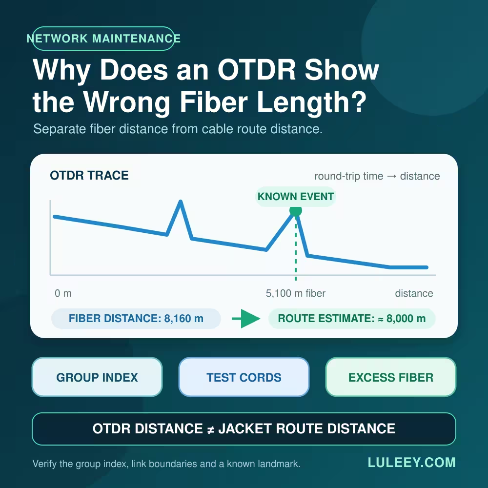
An OTDR wrong Fiber Length reading does not necessarily mean the tester is broken. An OTDR times the round trip of a light pulse and converts that time into distance. A wrong group-index setting, a launch-cable offset, excess fiber inside the cable, or a misidentified end event can all move the displayed result.
Before changing the instrument, first decide what you are comparing: optical fiber length, cable-jacket length, mapped route distance, or the distance between two trace markers. Those numbers do not always mean the same thing.
OTDR Wrong Fiber Length: Quick Diagnosis
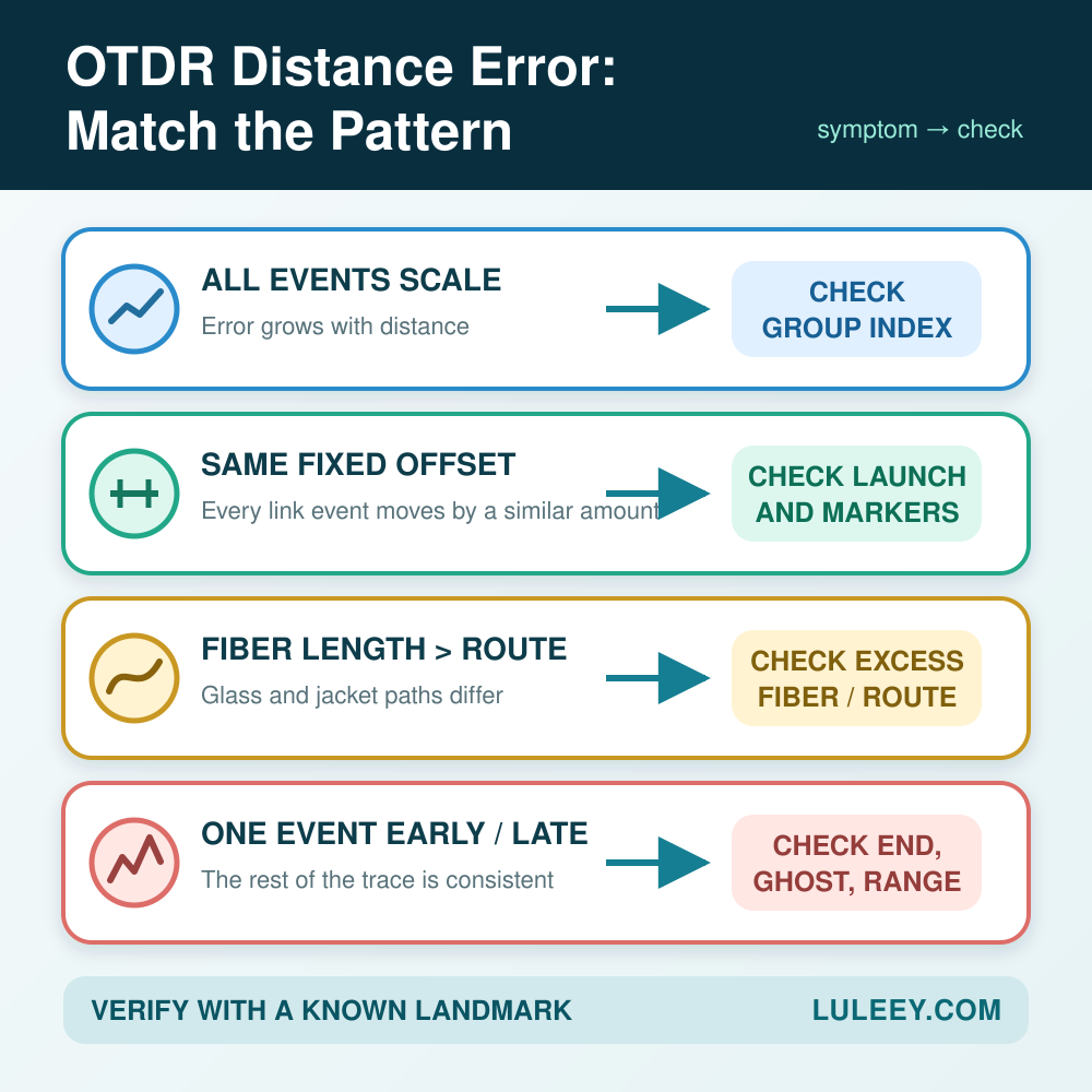
| What you see | Most likely area to check | First action |
|---|---|---|
| Every event is proportionally too far or too near | Group Index, also called IOR or GIR | Enter the fiber manufacturer’s value for the test wavelength |
| Every link event has roughly the same fixed offset | Launch-cable length, compensation or marker position | Place the start marker at the launch-to-link connection |
| OTDR fiber length is consistently longer than jacket or route length | Excess fiber inside the cable | Obtain the cable’s excess-fiber data or calculate a local correction factor |
| One extra event appears beyond the known end | Receive cable or an OTDR ghost | Map the receive cable and inspect the trace for a repeating reflection |
| The trace ends too early | Range, pulse width, dynamic range, splitter loss, bend or end threshold | Increase only the settings needed to reach the real end, then inspect the trace |
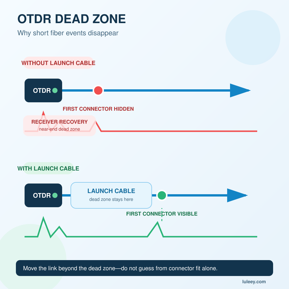
| A very short link gives unstable or merged events | Dead zone and distance resolution | Use a suitable Launch Cable and confirm whether an OTDR is appropriate for the link |
Do not correct all six symptoms by typing a different refractive index. Different error patterns need different fixes.
How an OTDR Turns Time into Distance
An OTDR launches a pulse into the fiber and measures returned Rayleigh backscatter and reflections. Because the light makes a round trip, the simplified distance relationship is:
Distance = c × round-trip time ÷ (2 × group index)
Here, c is the speed of light in vacuum and the group index represents the speed of the test pulse in that fiber at the selected wavelength.
The OTDR directly measures time. Distance is a calculated result. If the entered group index is wrong, the time data can be stable while every displayed event is placed at the wrong distance.thefoa.org
Cause 1: The Group Index Is Wrong
Use the effective group index specified for the exact fiber and test wavelength when it is available. Do not assume one generic value fits every G.652, G.657, OM3 or OM4 fiber.
The direction of the error is predictable:
- If the entered group index is lower than the fiber’s actual value, the OTDR calculates a distance that is too long.
- If the entered group index is higher than the actual value, the OTDR calculates a distance that is too short.
A group-index error also scales with distance. For example, if a setting creates roughly a 1% distance error, an event near 100 m may move by about 1 m, while an event near 10 km may move by about 100 m. The exact result depends on the ratio between the actual and entered values.
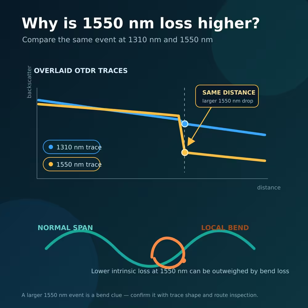
Group index can also differ with wavelength. When comparing 1310 nm and 1550 nm traces, verify the value used for each wavelength instead of assuming that a small distance difference proves the event moved.
Cause 2: Fiber Length Is Not Cable Length
An OTDR measures distance along the glass fiber. Jacket markings, construction drawings and geographic route measurements describe the cable or route.
Many cable designs contain excess fiber so the glass is not placed under the same tensile stress as the cable structure. The fiber may follow a helical or otherwise longer path inside the cable. As a result, an OTDR can correctly report more fiber than the length printed on the jacket.
FOA describes roughly 1–2% excess fiber as common, while Corning’s outside-plant example says approximately 2–3% is usual in that context. These are explanatory ranges, not universal limits. Ribbon, tight-buffered and loose-tube constructions can differ, and the actual cable data takes priority.thefoa.org
This distinction matters when locating a buried break. A result of 8,160 m along the fiber does not automatically mean the fault is 8,160 m along the road or duct.
Cause 3: The Launch or Receive Cable Is Included
A launch cable provides backscatter before the first connection of the installed link. A receive cable provides fiber after the last connection so that the far-end connector can be evaluated.
Both cables also occupy distance on the trace.
If the OTDR displays distance from its front panel, the first installed-link event appears after the launch-cable length. There are two valid ways to report the link itself:
- Set Marker A at the launch-to-link connection and Marker B at the link-to-receive-cable connection.
- Use the instrument’s launch/receive compensation function after entering or measuring the correct reference-cable lengths.
Do not do both unless the instrument procedure specifically requires it. Double compensation can create a new error.
If every installed event is displaced by almost the same number of metres, suspect a boundary or compensation error before changing the group index.
Cause 4: The OTDR Chose the Wrong End Event
Automatic event analysis is useful, but it is not a substitute for the trace.
The apparent end can be wrong when:
- The selected range does not cover the full link.
- The pulse is too narrow to provide enough returned signal after a long or high-loss path.
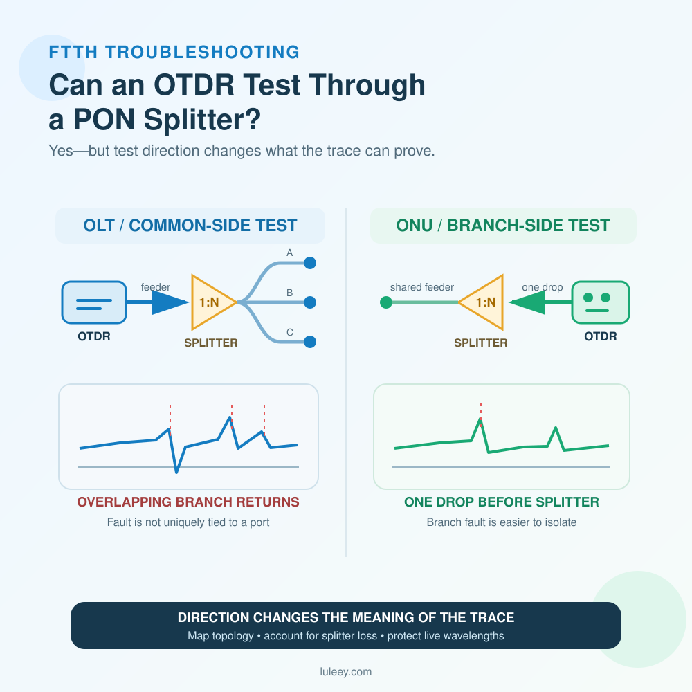
- A splitter, severe bend or bad connection drops the trace near the noise floor.
- The end threshold identifies a large loss as the end of fiber.
- A receive cable is mistaken for part of the installed link.
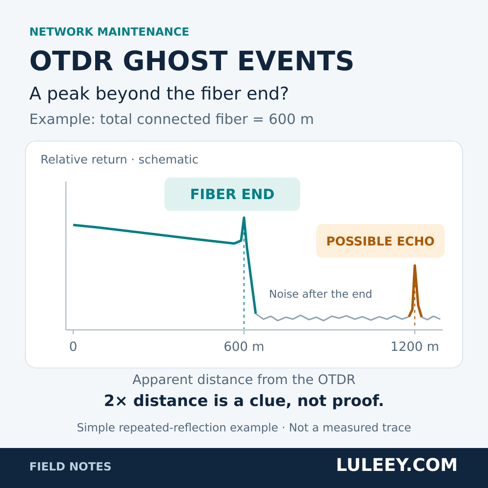
- A strong reflection creates a ghost beyond the real end.
- Two closely spaced end events merge because of the selected pulse width and dead zone.
If a peak appears beyond all known connected fiber, compare it with LuLeey’s guide to OTDR ghost events. If the beginning or end connector cannot be separated from a large reflection, review the OTDR dead-zone guide.
Group-Index Error or Cable Excess? Use the Pattern
| Check | Group-index mismatch | Excess fiber in cable |
|---|---|---|
| What is wrong? | Time is converted with the wrong pulse velocity | The glass path is physically longer than the cable or route |
| Effect on trace | Every optical event is scaled incorrectly | OTDR may correctly show a longer fiber path |
| Best evidence | Fiber data sheet and wavelength-specific group index | Cable construction data, jacket marks and known route landmarks |
| Correct response | Enter the correct group index | Apply a cable-specific route correction when locating field events |
| What not to do | Guess a value until one event looks right | Call a correct fiber measurement an instrument fault |
Do not hide excess fiber by changing the group index if you still need a technically correct fiber-length record. Keep the optical measurement and the route conversion as separate documented values.
A Practical Cable-Route Correction Example
Suppose a known handhole is 5,000 m from the test origin according to verified cable-route records. The same physical event appears at 5,100 m on the OTDR after the correct group index and link boundaries have been set.
Calculate a local correction factor:
Route correction factor = known route distance ÷ measured fiber distance
Route correction factor = 5,000 ÷ 5,100 = 0.9804
If a break then appears at 8,160 m of fiber distance in the same cable section:
Estimated route distance = 8,160 × 0.9804 ≈ 8,000 m
This estimate is only valid when the known landmark and suspected fault are in a cable section with comparable construction and slack practice. Service loops, a change of cable type, rerouting or undocumented splices can invalidate one correction factor.
For excavation or dispatch, combine the corrected distance with route drawings, handhole records and a test from the opposite end. Never treat the OTDR number alone as a geographic coordinate.
A Reliable Retest Workflow
1. Save the original trace
Record the test wavelength, range, pulse width, averaging time, group index, launch and receive cables, compensation settings and automatic thresholds. Do not overwrite the evidence.
2. Define the distance you need
Specify whether the goal is total fiber length, installed-link length between connectors, cable-jacket length or field-route distance to a fault.
3. Verify the group index
Use the fiber or cable manufacturer’s wavelength-specific value where available. If the exact fiber is unknown, label the result as an estimate rather than silently treating a default as exact.
4. Mark the real link boundaries
Identify the OTDR port, launch cable, installed link, far-end connector and receive cable on the trace. Correct any compensation entry before interpreting event distances.
5. Make the end visible
Choose a range that extends beyond the expected end. Use the shortest pulse that still reaches the end with a usable signal-to-noise ratio, and increase averaging before using an unnecessarily wide pulse.
6. Inspect the trace, not only the event table
Confirm that the selected end has a physical counterpart. Look for stable backscatter before it, the expected receive cable after it, or a genuine final reflection followed by noise.
7. Test from the other end
With consistent group-index and boundary settings, an event at distance x from End A should appear at approximately total fiber length − x from End B. Large disagreement points to boundary, event-pairing, trace-quality or setup problems.
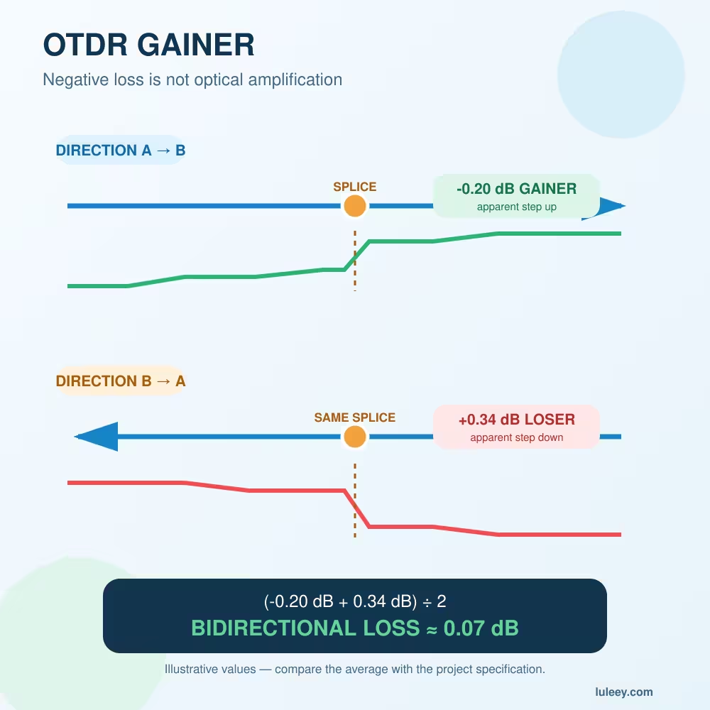
If opposite-direction event loss looks negative in one direction and high in the other, that is a separate backscatter issue; use the OTDR gainer guide rather than changing distance settings.
Common Mistakes
- Comparing OTDR fiber distance directly with a road-map distance
- Copying a generic refractive index without checking wavelength or fiber data
- Subtracting the launch cable twice
- Treating the end of a receive cable as the end of the installed link
- Trusting an automatic end label after a splitter or severe bend
- Using a very wide pulse on a short link and then reporting merged events as exact locations
- Adjusting group index only to make one known event match while ignoring the rest of the trace
- Dispatching a repair crew without applying cable-route correction and checking from both ends
Practical Next Step
Add six fields to every OTDR test record: fiber type, wavelength, group index, launch-cable boundary, receive-cable boundary and route correction factor. Then label each reported number as fiber distance, link distance or route distance.
That small documentation change prevents a technically correct fiber measurement from being mistaken for a wrong cable location—and makes later fault finding much faster.


 SFP/SFP+ (1G/2.5G/5G/10G)
 SFP-T (1G/2.5G/10G)
 AOC Cable 10G/25G/40G/100G
 DAC Cable 10G/25G/40G/100G
 QSFP28 QSFP+ SFP28 100G/40G/25G
 Copper to Fiber Media Converters
 Fiber Media Converter PCBA Board
 OEO Fiber Media Converters
 Serial to Fiber Media Converters
 Video to Fiber Media Converters
 1000M GPON/EPON ONU
 10G EPON ONU/XG-PON/XGS-PON
 2.5G GPON/XPON STICK SFP ONU
 POE GPON/EPON ONU
 Wireless GPON/EPON ONT
 EPON OLT
 GPON OLT
 SFP PON Module
 Industrial Switches
 Managed Switches
 POE Switches
 Unmanaged Switches
 MTP/MPO Fiber Cables
 Fiber Optic Cassettes
 Fiber Optic Loopback
 Optic Cables and Fiber Pigtails
 Optical Splitters and Splitter Box
 Fiber Flange Connectors
 Optical Adapters
 Optical Attenuator
 Quick Connector and Connector Panel
 CATV Amplifier
 CATV Optical Receiver
 Visual Fault Locator
 OTDR
OTDR Optical Power Meter
 Fiber Optic Identifier
 Fiber Optic Cleaners
 Fiber Cleavers & Fiber Strippers
 Copper Tools


