Customs duties are the responsibility of customers, but standard logistics support DDP to most countries, duty-free such as US, DE, UK, CA, FR, IT, PL, AT, JP…





















































OTDR Gainer: Why Does a Splice Show Negative Loss?
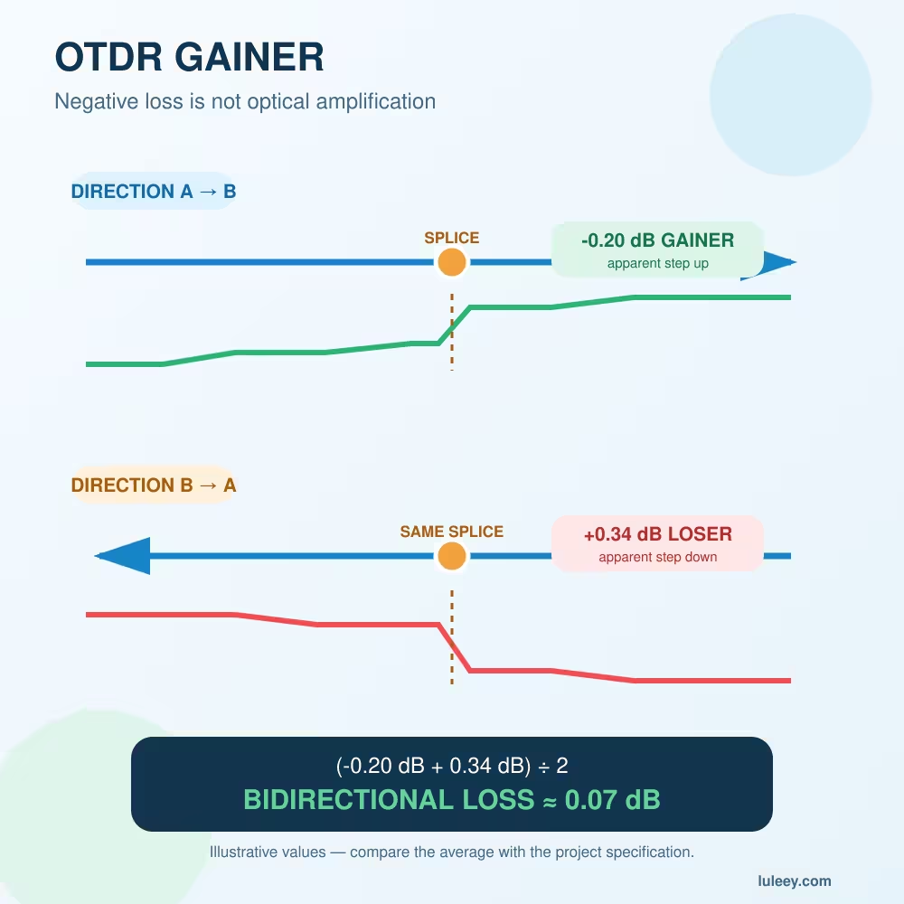
An OTDR Gainer is an event that appears to increase optical power on an OTDR trace. The event table may report a negative loss such as -0.20 dB, even though a passive splice cannot amplify light.
This usually happens because the two joined fibers return different amounts of Rayleigh backscatter to the OTDR. The instrument interprets the change in returned backscatter as part of the event loss.
Test the same splice from both ends and average the two signed readings. A gainer in one direction normally becomes a higher-loss event—a “loser”—in the opposite direction. The bidirectional average cancels most of the backscatter mismatch and provides a much better estimate of the splice loss.
Do not automatically pass the splice because one direction shows gain, and do not automatically resplice it because the other direction shows high loss.
OTDR Gainer: Quick Interpretation
| Direction A→B | Direction B→A | Likely interpretation | Next step |
|---|---|---|---|
| Negative loss | Higher positive loss | Typical gainer/loser pair caused by backscatter difference | Average the signed results |
| Low positive loss | Similar low positive loss | Fibers have similar backscatter; result is consistent | Compare with project limit |
| High positive loss | High positive loss | Real splice loss, bend or poor event analysis is more likely | Inspect the trace and splice |
| Negative or unstable in both tests | No consistent paired event | Wrong event pairing, dead zone, noise or setup problem | Correct settings and retest |
| Reflective peak in both directions | Connector or mechanical interface may be involved | Not a simple fusion-splice gainer | Inspect the physical event |
A negative one-way number is not proof of a good splice. The two directions and complete trace must agree with the physical route.
Why a Passive Splice Can Look Like It Has Gain
An OTDR does not place a power meter after every splice. It launches a pulse and measures the small amount of light that returns through Rayleigh backscatter and reflections.
The backscatter level depends on fiber properties. Two single-mode fibers can meet the same general application category while still having different:
- Mode field diameters
- Backscatter coefficients
- Attenuation characteristics
- Refractive-index profiles
- Manufacturing designs or tolerances
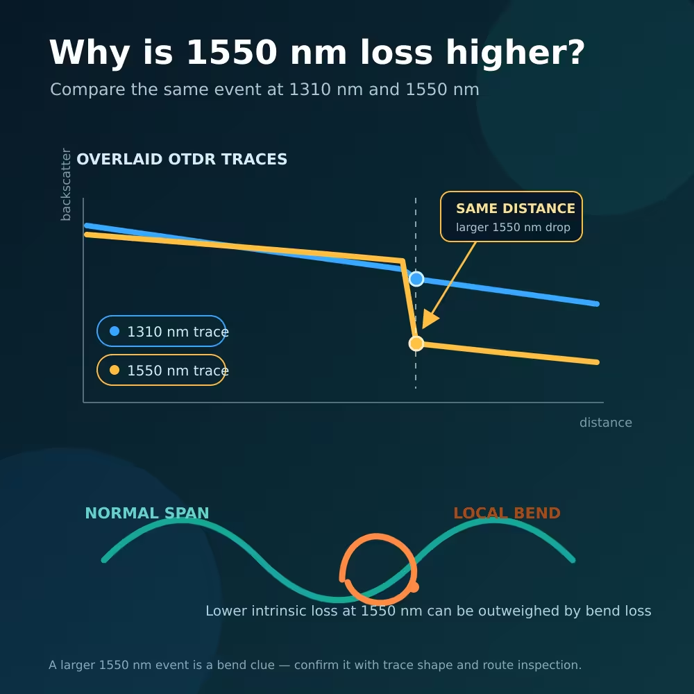
When an OTDR pulse crosses from a lower-backscatter fiber into a higher-backscatter fiber, more light returns from the section after the splice. The trace steps upward. If that change is larger than the real splice loss, the event table reports negative loss: an OTDR gainer.
When the link is tested from the opposite end, the pulse crosses the same fibers in reverse order. The backscatter level steps downward, so the OTDR reports more loss than the splice actually has.
The Fiber Optic Association’s OTDR guide describes this directional error and recommends testing both ways and averaging the event results.
What Mode Field Diameter Has to Do with It
Mode field diameter, or MFD, describes the effective width of the optical field propagating in a single-mode fiber. It is not simply the physical core diameter.
Differences in fiber design and MFD can change the amount of backscatter seen by an OTDR. A splice between fibers with different properties may therefore show different event loss from opposite directions.
ITU-T G.650.1 includes a bidirectional backscatter-difference method in which changes across a splice are measured from both directions and related to mode field diameter. This supports the central point: backscatter across a splice is directional as an OTDR measurement, even though the passive splice does not provide real gain.
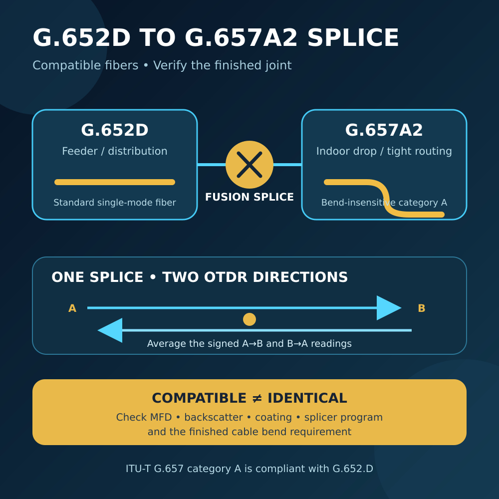
A gainer can occur when joining different fiber designs, production batches or manufacturers. Joining standard and bend-insensitive single-mode fibers is one possible situation, but the labels alone do not predict the result. Check the exact fiber specifications rather than assuming every G.652-to-G.657 splice will behave the same way.
For multimode fiber, core size and launch conditions add further uncertainty. Do not intentionally mix 50/125µm and 62.5/125µm fiber merely because the connector fits.
How to Calculate Bidirectional Splice Loss
Keep the signs exactly as reported in the OTDR’s loss field.
Suppose the same splice produces:
- A→B result:
-0.20 dB - B→A result:
+0.34 dB
Calculate:
Bidirectional splice loss = (-0.20 dB + 0.34 dB) ÷ 2
Bidirectional splice loss = 0.07 dB
The corrected result is approximately 0.07 dB, not -0.20 dB and not 0.34 dB.
These are illustrative values, not a universal pass/fail limit. Compare the averaged result with the project specification, fiber type, splice method and measurement uncertainty.
What if the average is still negative?
A slightly negative average can result from noise, marker placement, automatic event analysis, short baselines or measurement uncertainty. Do not silently change it to zero.
Review:
- Whether the same physical event was paired
- Whether both tests used equivalent settings
- Whether stable backscatter exists on both sides of the event
- Whether a nearby reflection or dead zone affected the calculation
- Whether launch and receive cables were included correctly
Retest before making an acceptance decision.
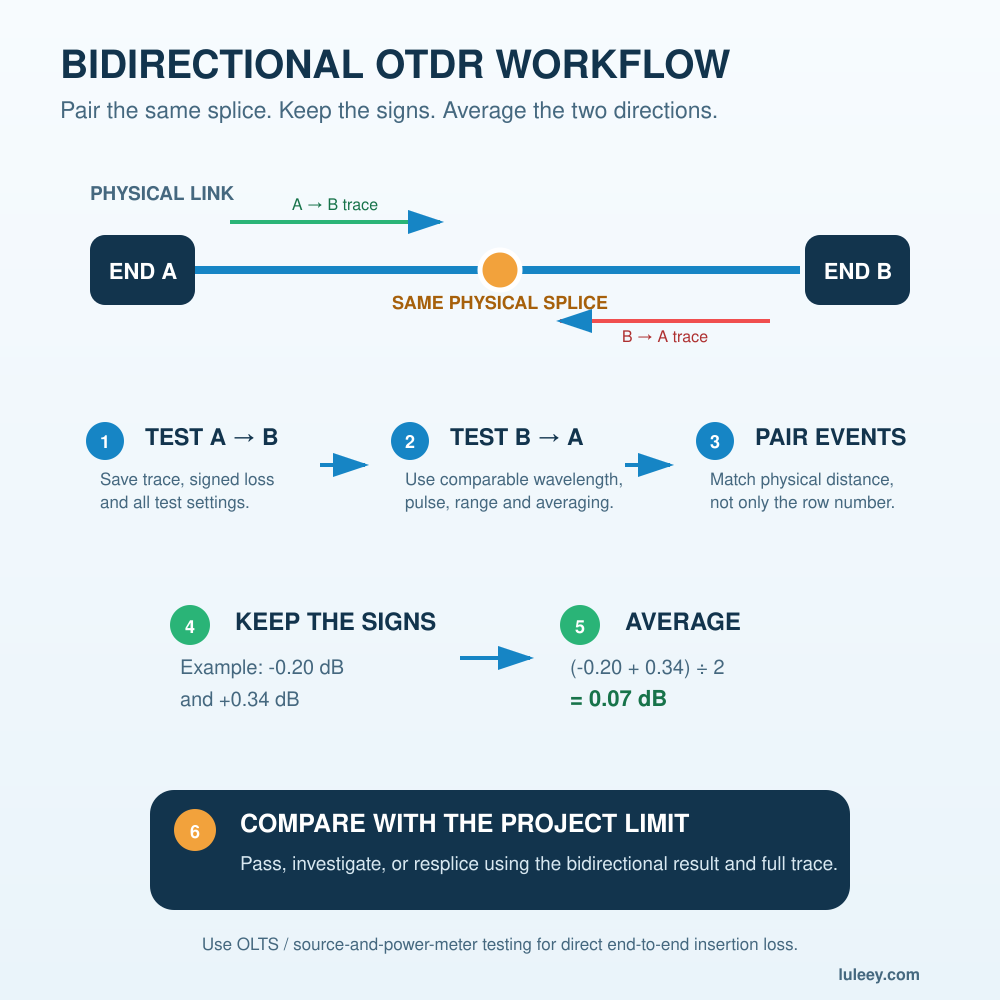
How to Perform a Valid Bidirectional OTDR Test
Step 1: Document the physical link
Record the route, total length, splice plan, connector locations and expected fiber types.
A splice measured 4km from End A should appear at approximately the total link length minus 4km when measured from End B.
Step 2: Use suitable launch and receive cables
Use a launch cable at the active OTDR end and a receive cable at the far end. When you reverse the test, the former receive end becomes the launch side.
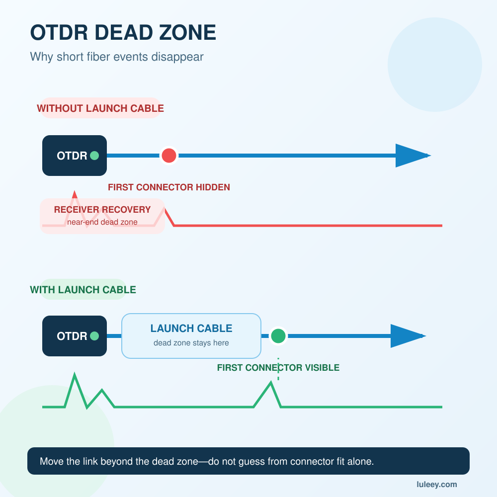
The cables must match the relevant fiber and connector interfaces and be long enough for the selected pulse and range. LuLeey’s guide to OTDR dead zones and launch cables explains how reference fibers reveal the first and last connections.
Step 3: Keep test conditions comparable
Use the same:
- Wavelength
- Pulse width
- Range
- Averaging time or acquisition quality
- Group-index setting
- Event-analysis method
Changing the pulse width or wavelength between directions introduces another variable.
Step 4: Test from End A
Save the trace and event table. Record the event distance, signed loss, reflectance where applicable, wavelength and test settings.
Do not look only at the automatic event table. Confirm that the trace has stable backscatter sections on both sides of the splice.
Step 5: Test from End B
Move the OTDR to the other end or use an approved remote test arrangement. Repeat the test under equivalent conditions.
Step 6: Pair the same physical events
Event numbers may reverse. “Event 6” from End A may not remain “Event 6” from End B.
Use distance from each endpoint, total link length, the splice plan and nearby known events to confirm the match.
Step 7: Average the signed readings
For each paired non-reflective splice:
Average loss = (A→B signed loss + B→A signed loss) ÷ 2
Preserve negative signs during the calculation.
Step 8: Compare with the acceptance criteria
Use the project’s stated limit and test method. If the bidirectional average exceeds the limit, investigate the splice, bend, fiber compatibility and measurement setup.
When Should You Resplice an OTDR Gainer?
Do not resplice only because the event is negative in one direction or high in the other.
Resplice or investigate when:
- The bidirectional average exceeds the project limit.
- Both directions show excessive positive loss.
- The trace shows a bend, reflection or abnormal event shape.
- The event changes after cable movement or environmental stress.
- The splice record identifies damaged or incompatible fibers.
- End-to-end insertion loss is outside the link budget.
- Splicer records indicate contamination, poor cleaving or alignment problems.
Repeatedly resplicing a backscatter-mismatch event may produce nearly the same one-way readings. The fiber properties have not changed, so the gainer/loser pattern can remain after a physically good splice.
Common OTDR Gainer Mistakes
Treating negative loss as real amplification
A passive fusion splice does not add optical power. The upward step is an OTDR backscatter effect.
Deleting the negative sign before averaging
If -0.20 dB is changed to +0.20 dB, the directional backscatter correction no longer works.
Averaging event numbers instead of physical events
Reverse-direction event tables may use a different order. Pair by physical location, not only by row number.
Using different wavelengths or pulse widths
Different settings change resolution, noise and measured event loss. Keep the acquisitions comparable.
Ignoring the trace slope
A section with a visibly different backscatter slope or level is a clue that the joined fibers differ. Automatic analysis may hide that context.
Using one-way OTDR loss as total link loss
For direct end-to-end insertion loss, use a calibrated light source and power meter or OLTS. OTDR event analysis and insertion-loss testing answer different questions.
OTDR Gainer vs a Real Bad Splice
| Check | Typical gainer/loser pair | More likely real high-loss splice |
|---|---|---|
| A→B reading | Negative or unusually low | Positive and high |
| B→A reading | Positive and unusually high | Positive and high |
| Bidirectional average | Much smaller than the high one-way value | Remains above the limit |
| Trace around event | Backscatter level changes between fiber sections | Clear loss remains from both directions |
| Effect of resplicing | Directional difference may remain | Loss may improve |
| End-to-end loss | May still be normal | May be excessive |
This table is a diagnostic guide, not a substitute for the project test specification.
Choosing the Right LuLeey Test Setup
If the first or last splice is hidden, solve the reference-cable and dead-zone issue before interpreting a gainer.
LuLeey’s single-mode OTDR launch cable box provides multiple connector and length selections. Confirm the OTDR port, network connector, polish, fiber type, wavelength and required distance before ordering.
Users new to this measurement method can first review What Are TDR and OTDR? for the basic difference between copper time-domain testing and optical backscatter testing.
Final Answer
An OTDR gainer is normally an apparent Negative Splice Loss caused by different backscatter levels in the fibers on each side of an event. It is not real optical amplification.
The correct response is:
- Test the link from both ends with comparable settings.
- Match the same physical splice in both traces.
- Preserve the positive and negative signs.
- Average the two signed event-loss readings.
- Compare the bidirectional result with the project limit.
- Use insertion-loss testing when the total link loss must be certified.
Resplice only when the corrected result or other evidence shows a real problem. A one-way gainer or loser by itself is not enough.




 SFP/SFP+ (1G/2.5G/5G/10G)
 SFP-T (1G/2.5G/10G)
 AOC Cable 10G/25G/40G/100G
 DAC Cable 10G/25G/40G/100G
 QSFP28 QSFP+ SFP28 100G/40G/25G
 Copper to Fiber Media Converters
 Fiber Media Converter PCBA Board
 OEO Fiber Media Converters
 Serial to Fiber Media Converters
 Video to Fiber Media Converters
 1000M GPON/EPON ONU
 10G EPON ONU/XG-PON/XGS-PON
 2.5G GPON/XPON STICK SFP ONU
 POE GPON/EPON ONU
 Wireless GPON/EPON ONT
 EPON OLT
 GPON OLT
 SFP PON Module
 Industrial Switches
 Managed Switches
 POE Switches
 Unmanaged Switches
 MTP/MPO Fiber Cables
 Fiber Optic Cassettes
 Fiber Optic Loopback
 Optic Cables and Fiber Pigtails
 Optical Splitters and Splitter Box
 Fiber Flange Connectors
 Optical Adapters
 Optical Attenuator
 Quick Connector and Connector Panel
 CATV Amplifier
 CATV Optical Receiver
 Visual Fault Locator
 OTDR
OTDR Optical Power Meter
 Fiber Optic Identifier
 Fiber Optic Cleaners
 Fiber Cleavers & Fiber Strippers
 Copper Tools


