Customs duties are the responsibility of customers, but standard logistics support DDP to most countries, duty-free such as US, DE, UK, CA, FR, IT, PL, AT, JP…





















































Yes, you can normally splice G.652D to G.657A2 fiber. ITU-T defines G.657 category A fibers as compliant with G.652.D and as having the same transmission and interconnection properties. This makes a G.652D feeder joined to a G.657A2 indoor drop a normal design option when both finished cables and the splice process meet the project requirements.
Compatible does not mean identical. The fibers may have different mode field diameters, backscatter coefficients, coatings and bend behavior. A sound splice can therefore show apparent gain from one OTDR direction and higher loss from the other. The correct response is to test from both ends, pair the same physical event and average the two signed readings.
Do not approve the link from the fusion splicer’s estimated loss alone. Verify the splice, cable routing and end-to-end link using the acceptance method specified for the project.
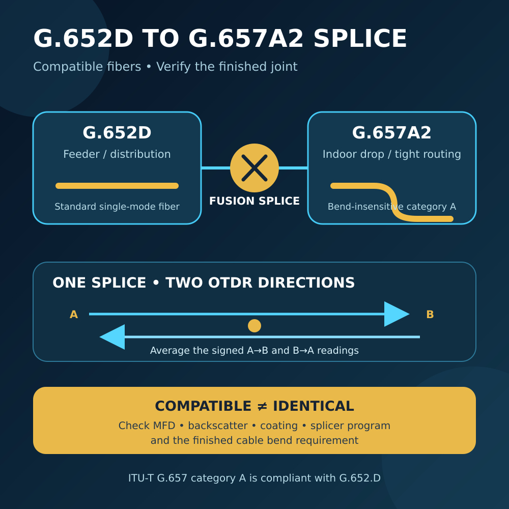
Splice G.652D to G.657A2 Fiber: Quick Answer
| Question | Practical answer | What still needs checking |
|---|---|---|
| Can G.652D and G.657A2 be fusion-spliced? | Normally yes | Exact fiber and cable datasheets, splicer program and project limits |
| Are the two fibers identical? | No | MFD, backscatter, coating, bend performance and manufacturer tolerances |
| Must both sides use the same connector polish? | Not at a bare fusion splice | APC/UPC still matters at every connectorized interface |
| Is a negative OTDR loss a real optical gain? | No | Test the same splice from the opposite end and average signed values |
| Should every one-way high-loss result be respliced? | No | Check the reverse trace, event shape, splice record and direct link loss |
| Can G.657A2 be bent to 7.5mm in every cable assembly? | Not automatically | Cable construction, installation method, lifetime and supplier instructions |
The standards establish fiber compatibility. Field quality still depends on preparation, alignment, protection, routing and measurement.
Why G.652D and G.657A2 Are Compatible
ITU-T G.652 specifies widely used single-mode optical fiber and cable. G.652.D is commonly installed in feeder, distribution and general transport links.
ITU-T G.657 specifies bending-loss-insensitive Single-Mode Fiber. Its current 2024 edition says that category A fibers are a subset of G.652.D. They are compliant with G.652.D and have the same transmission and interconnection properties.
The standard identifies two category A subcategories:
- G.657.A1: appropriate for a minimum design radius of 10mm.
- G.657.A2: appropriate for a minimum design radius of 7.5mm.
This improved bend performance is useful near customer premises, wall outlets, cabinets, corners and other restricted spaces. It does not make the fiber immune to bends, crushing, staples or long-term mechanical stress.
The 7.5mm figure is a fiber-category design value under the standard’s test framework. A finished drop cable, transparent indoor cable or patch cord can require a larger installation radius because its coating, strength members, jacket, connector boot and installation method also matter.
Compatible Does Not Mean Every Splice Reads the Same
Two fibers can be standards-compatible while differing within their permitted manufacturing ranges. Important variables include:
- Mode field diameter at the splice wavelength
- Core-to-cladding concentricity
- Cladding diameter and geometry
- Refractive-index profile
- Rayleigh backscatter coefficient
- Coating diameter and stripping behavior
- Cleave quality and end-face angle
- Splicer alignment method and arc program
Mode field diameter, or MFD, is the effective width of the optical field carried by a single-mode fiber. It is not simply the physical glass-core diameter.
If the two mode fields differ, a splice may have some true coupling loss even when the glass is aligned well. The same difference can also change the backscatter level seen by an OTDR, producing a much larger directional measurement difference than the real splice loss.
That is why the fiber names alone cannot predict an exact splice-loss number. Use the exact manufacturer specifications and the project’s acceptance criteria.
Why the OTDR May Show Negative Loss
An OTDR estimates splice loss from the backscatter levels before and after the event. It does not place a direct optical power meter on the far side of each splice.
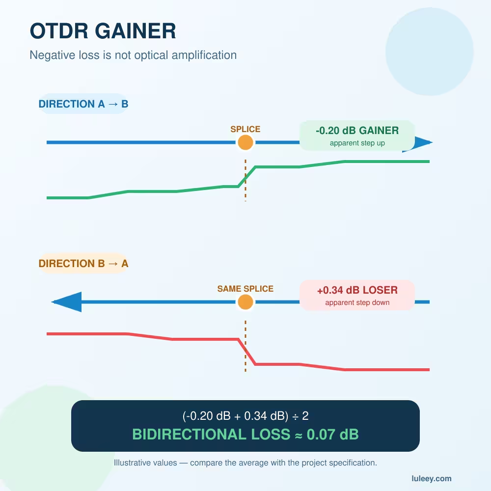
Suppose the test pulse travels from a lower-backscatter fiber into a higher-backscatter fiber. The trace level after the splice can step upward. If that upward change is larger than the real joint loss, the event table reports a negative value—often called a gainer.
Reverse the test direction and the same transition usually becomes a downward backscatter step. The OTDR then reports a higher positive loss, sometimes called a loser.
For example:
- End A to End B:
−0.12 dB - End B to End A:
+0.24 dB
Average the signed values:
Bidirectional splice loss = (−0.12 dB + 0.24 dB) ÷ 2 = 0.06 dB
The example shows the calculation only; 0.06dB is not a universal acceptance limit.
ITU-T G.650.1 defines test methods for single-mode fiber attributes, including backscatter-related methods. LuLeey’s guide to OTDR gainers and negative splice loss provides the full trace-pairing workflow.
Do not remove the negative sign before averaging. −0.12 + 0.24 is not the same as +0.12 + 0.24.
How to Tell a Backscatter Mismatch from a Bad Splice
| Evidence | More consistent with a gainer/loser pair | More consistent with real splice loss |
|---|---|---|
| A→B event | Negative or unusually low | Positive and high |
| B→A event | Higher positive value | Also positive and high |
| Signed bidirectional average | Much smaller than the high one-way reading | Remains above the project limit |
| Trace level | Clear baseline change between fiber sections | Loss remains without only a baseline reversal |
| After resplicing | Directional pattern may remain | Result may improve if preparation caused the loss |
| Direct end-to-end loss | May remain normal | May also be excessive |
Resplice or investigate when both directions remain high, the signed average fails the project limit, the event is reflective, the splice changes with movement, or the end-to-end link loss is excessive.
Repeatedly resplicing a normal backscatter mismatch may reproduce nearly the same directional pattern because the fiber properties have not changed.
Select the Splicer Program from the Actual Fibers
Do not choose a fusion program from jacket color or the words “single mode” alone.
Before splicing, identify:
- Fiber type on both sides
- Fiber manufacturer and part number when available
- Coating diameter and required holder
- Stripping and cleaning method
- Cleave-length requirement
- Recommended fusion program or automatic analysis mode
- Required splice-protector sleeve
Many modern core-alignment splicers can analyze standard and bend-insensitive single-mode fibers and select or recommend a suitable program. That capability still depends on the splicer model, electrode condition, firmware, calibration and fiber preparation.
Use a manual or custom arc program only when the splicer or fiber supplier provides the procedure. An incorrect arc can create bubbles, necking, excessive deformation or weak mechanical strength.
The loss estimate displayed by a fusion splicer is calculated from images and an internal model. It is useful for immediate quality control, but it is not a direct end-to-end optical loss measurement.
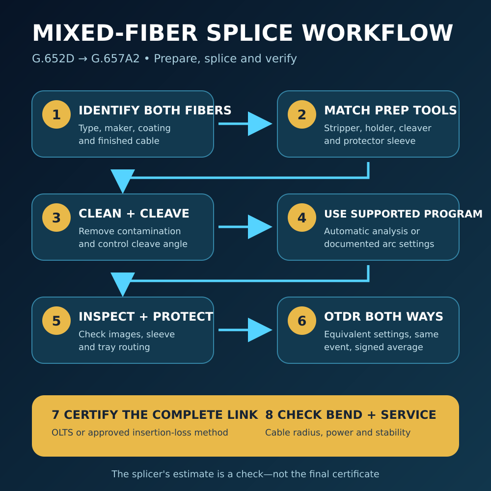
A Practical Fusion-Splicing Workflow
Step 1: Confirm the exact cable and fiber
Record the cable labels, fiber type, supplier and route. Do not rely on buffer or jacket color as proof of G.652D or G.657A2.
Step 2: Check the mechanical preparation
Confirm that the stripper, holder, cleaver and protection sleeve match the actual coating and cable construction. G.652D and G.657A2 may be optically compatible while their finished cable structures require different preparation.
Step 3: Clean and cleave both ends
Remove the coating using the approved tool, clean the bare glass and make a consistent cleave. Contamination and poor cleave angle can create real loss that compatibility cannot correct.
Step 4: Select the documented splice program
Use the program recommended for the two fiber types or the splicer’s supported automatic analysis. Complete arc calibration when required for the environment and equipment.
Step 5: Inspect the fusion result
Review the fiber images and the splicer’s estimated loss. Reject visible bubbles, severe offsets, abnormal diameter changes or other defects according to the equipment and project procedure.
Step 6: Protect and route the splice
Complete the specified proof test if the procedure requires one, install the protector sleeve and secure it in the tray without microbending or pressure. Respect the finished cable’s routing radius, not only the bare-fiber category value.
Step 7: Test from both ends
Use equivalent OTDR wavelength, pulse width, range, averaging and event-analysis settings in both directions. Pair the same physical splice by distance and route records, then average the signed event-loss readings.
Step 8: Validate the complete link
Use the project’s approved light-source and power-meter or OLTS method when direct end-to-end insertion loss must be certified. Confirm service wavelengths, connectors, reflections and total link budget as required.
Do APC and UPC Matter at the Fusion Splice?
No. APC and UPC describe connector end-face polish. A fusion splice joins bare glass and has no APC or UPC polish.
They still matter elsewhere in the finished link. Do not directly mate an APC connector to a UPC adapter or connector just because both use SC, LC or FC bodies. Verify connector family and polish at the OLT, ONU, patch panel, wall outlet, test cord and instrument.
Also distinguish these two situations:
- Fusion splice: permanent bare-glass joint made with a fusion splicer.
- Mechanical connector or adapter: detachable interface whose polish, alignment sleeve, cleanliness and reflectance affect performance.
A high reflection on an OTDR trace is not typical evidence of a simple fusion-splice MFD mismatch. Check whether a connector, mechanical splice or contaminated interface is present at that location.
Does G.657A2 Remove All Bend-Loss Risk?
No. G.657A2 has much better macrobending performance than conventional G.652D, but bend loss still depends on:
- Bend radius
- Number of turns
- Wavelength
- Length exposed to the bend
- Finished cable construction
- Installation pressure and long-term strain
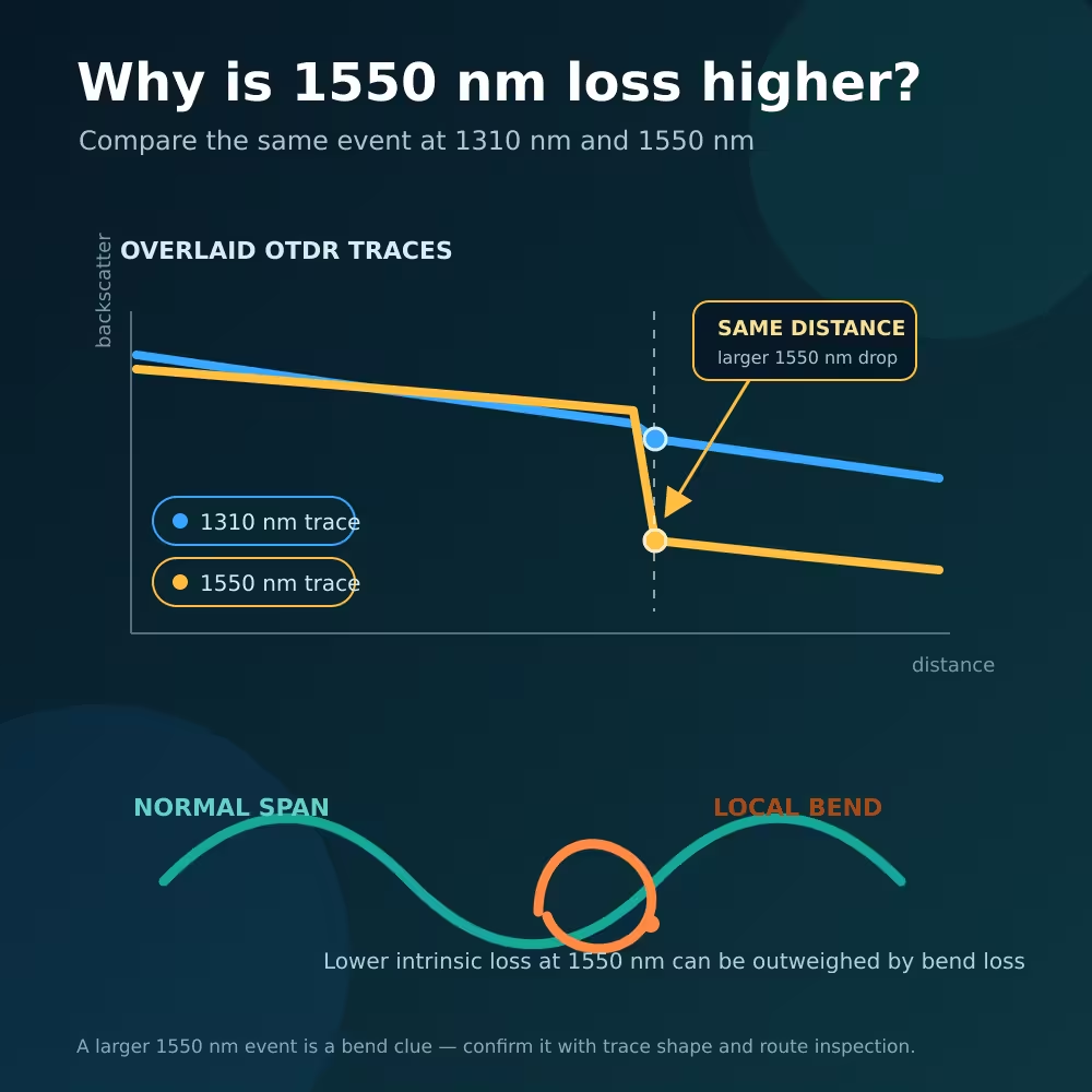
ITU-T G.657 notes that bend loss generally increases at longer wavelengths and that installed cable performance depends on the cable and installation method. Flat staples, sharp pinches, crushed corners and tight ties remain poor practice.
Use Bend-Insensitive Fiber to increase installation margin—not as permission to ignore the cable datasheet.
Applying the Method to LuLeey Fiber Products
LuLeey’s G.652D bare fiber and OTDR test-fiber page lists single-mode G.652D fiber, 1310nm attenuation of no more than 0.36dB/km, 1550nm attenuation of no more than 0.22dB/km and a listed mode field diameter of 8.6–9.5μm.
The G.657A2 bare fiber page lists G.657A2 material, multiple connector choices and bare-fiber/test lengths. Its current specification table shows “Minimum bending radius 15” without a unit or separate bare-fiber/cable test condition. Do not use that field as a final installation rule until LuLeey confirms the unit, sample construction and measurement condition.
For installed indoor cabling, LuLeey’s G.657A2 FTTR transparent fiber cable is listed as a bend-resistant indoor cable with SC/APC, SC/UPC, FC/APC, LC/UPC and headless options. Choose the connectorized or headless version from the actual termination method; connector availability does not replace a splice and optical-budget review.
Before ordering fiber for a mixed link, provide LuLeey with:
- Exact G.652D and G.657A2 fiber or cable part numbers
- Bare-fiber coating and finished cable construction
- Route and minimum installed bend radius
- Splicer model, firmware and holder type
- Required wavelengths and link distance
- Connector family and APC/UPC polish
- Project splice-loss and end-to-end loss limits
- OTDR launch/receive fiber type and bidirectional test plan
Final Answer
You can normally splice G.652D to G.657A2 because G.657 category A fibers are defined as G.652.D-compliant and share the required transmission and interconnection properties.
For a reliable field result:
- Identify the exact fibers and cable constructions.
- Match the stripping, holding and protection tools to their coatings.
- Use a documented or supported automatic fusion program.
- Inspect and protect the splice without creating a bend.
- Test the same event from both ends with comparable OTDR settings.
- Average the signed directional readings.
- Use direct insertion-loss testing when the complete link must be certified.
- Apply the finished cable’s routing rules rather than treating 7.5mm as universal permission.
A one-way OTDR Gainer does not prove a perfect splice, and a one-way loser does not automatically justify resplicing. The bidirectional result, trace shape, splice record and total link performance should agree.

 SFP/SFP+ (1G/2.5G/5G/10G)
 SFP-T (1G/2.5G/10G)
 AOC Cable 10G/25G/40G/100G
 DAC Cable 10G/25G/40G/100G
 QSFP28 QSFP+ SFP28 100G/40G/25G
 Copper to Fiber Media Converters
 Fiber Media Converter PCBA Board
 OEO Fiber Media Converters
 Serial to Fiber Media Converters
 Video to Fiber Media Converters
 1000M GPON/EPON ONU
 10G EPON ONU/XG-PON/XGS-PON
 2.5G GPON/XPON STICK SFP ONU
 POE GPON/EPON ONU
 Wireless GPON/EPON ONT
 EPON OLT
 GPON OLT
 SFP PON Module
 Industrial Switches
 Managed Switches
 POE Switches
 Unmanaged Switches
 MTP/MPO Fiber Cables
 Fiber Optic Cassettes
 Fiber Optic Loopback
 Optic Cables and Fiber Pigtails
 Optical Splitters and Splitter Box
 Fiber Flange Connectors
 Optical Adapters
 Optical Attenuator
 Quick Connector and Connector Panel
 CATV Amplifier
 CATV Optical Receiver
 Visual Fault Locator
 OTDR
OTDR Optical Power Meter
 Fiber Optic Identifier
 Fiber Optic Cleaners
 Fiber Cleavers & Fiber Strippers
 Copper Tools


