Customs duties are the responsibility of customers, but standard logistics support DDP to most countries, duty-free such as US, DE, UK, CA, FR, IT, PL, AT, JP…





















































An SFP TX Bias Current high warning means that the transmitter laser is being driven above the module manufacturer’s programmed warning threshold. It deserves investigation, but one high current reading does not prove that the module has failed.
Start by reading the complete DDM or DOM snapshot: temperature, supply voltage, TX bias current, TX output power, RX power, warning and alarm thresholds, and status flags. Then compare the result with earlier readings from the same module under similar conditions.
The most concerning pattern is persistently rising bias current combined with falling TX power, a TX fault, increasing errors or link instability. High bias with stable TX power may be the module’s control loop compensating for temperature or gradual laser change. It can also be an inaccurate or incorrectly interpreted reading, especially when the host and transceiver combination has not been validated.
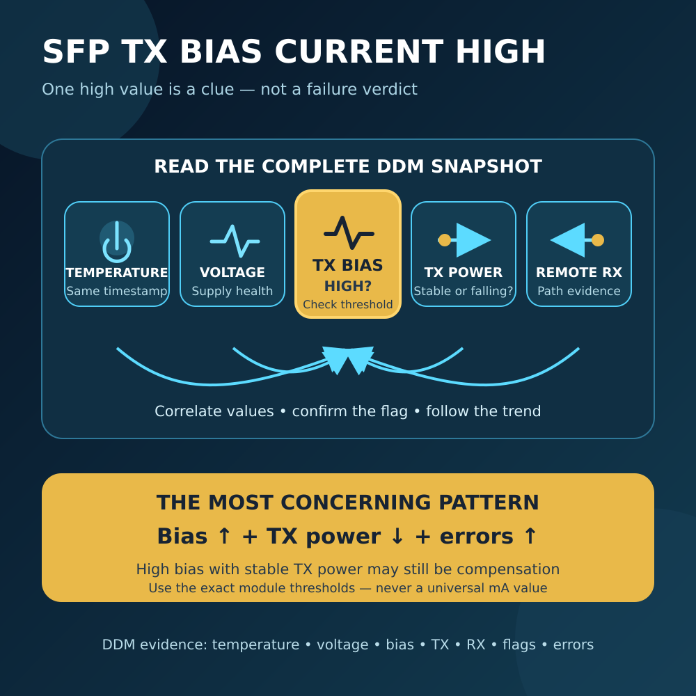
SFP TX Bias Current High: Quick Diagnosis
| What you observe | What it may mean | First useful action |
|---|---|---|
| High warning, stable TX power and no errors | Outside the manufacturer’s normal band; not necessarily immediate failure | Confirm the flag, record temperature and trend the same module |
| High alarm, TX fault or unstable link | More serious transmitter or operating-condition problem | Protect service, capture evidence and test a known-good supported module |
| Bias rises as the module warms, then stabilizes | Possible temperature-related control-loop response | Compare with the module’s temperature grade and a cold-to-warm baseline |
| Bias rises over weeks while TX power falls | Possible laser degradation or control problem | Schedule replacement testing before the link becomes unstable |
| High reading appears only in one host | Possible parsing, calibration or compatibility issue | Read the module in a supported host and compare raw thresholds and flags |
| High bias locally but only remote RX power is low | The transmitter and optical path may be separate issues | Compare local TX power with remote RX; inspect path loss if that difference changed |
| A brief flag appears during insertion or startup | Data may have been sampled before the module settled | Wait for valid data, reread and check whether the flag persists |
Do not compare one raw mA number with an unrelated module. Different laser technologies, wavelengths, reaches, temperature grades and manufacturers can use very different normal currents.
What Does TX Bias Current Measure?
TX bias current is the electrical current used to bias the transmitter laser at its operating point. A host usually displays it in milliamps.
The current is not Optical Power. DDM reports both values separately:
- TX bias current: how much laser-drive current the module reports.
- TX output power: the optical power the module reports at its transmitter output.
The current SNIA SFF-8472 specification defines DDM fields for module temperature, supply voltage, TX bias, TX output power and RX optical power. For internally calibrated SFP diagnostics, TX bias uses 2µA increments in a 16-bit field. The document also says bias-current accuracy is vendor-specific and must be better than ±10% of the manufacturer’s nominal value over the specified operating temperature and voltage.
That coding range is not a normal operating range. A value being representable in the DDM register does not make it safe for a particular laser.
Warning Is Not the Same as Alarm
SFF-8472 assigns four factory-programmed thresholds to each monitored analog quantity:
- High alarm
- Low alarm
- High warning
- Low warning
The transceiver manufacturer determines what is normal for that design. The standard explicitly expects thresholds to vary between technologies and implementations.
A TX Bias High Warning means that the current is outside the normally guaranteed bounds. SFF-8472 says a warning is not necessarily the cause of an immediate link failure. It also notes that a manufacturer may use unexpectedly high bias in a constant-power control loop as an end-of-life indicator.
A TX Bias High Alarm is more serious. The same specification describes alarms as conditions likely to be associated with a non-operational link and requiring immediate action.
Optional flags can be latched or non-latched, depending on the implementation. SFF-8472 recommends confirming an asserted flag with another read at least 100ms later. Your network device may poll much more slowly, so use the host’s actual collection interval when matching a DDM event to a link flap.
Do not dismiss a warning, but do not turn every warning into an emergency replacement. Preserve the timestamp, current value, all four thresholds and the other DDM readings first.
Why a High Bias Reading Does Not Always Mean Failure
The module may be maintaining optical output
Many optical transmitters regulate output using an internal monitor and control loop. As temperature or laser characteristics change, the module may adjust drive current to keep TX power within its target range.
This is why high bias plus normal TX power can be different from high bias plus falling TX power. The first pattern may show successful compensation. The second suggests that more drive is producing less reported optical output and deserves faster investigation.
This is an inference from the combined readings, not a universal diagnosis. The module vendor’s design and thresholds remain authoritative.
Temperature can move the operating point
Laser behavior changes with temperature, and compact SFP+ modules can become warm in dense cages. A bias value may rise after startup and settle when temperature stabilizes.
Compare the current with:
- The module’s commercial or industrial operating-temperature range
- Its own temperature warning and alarm thresholds
- A known cold-to-warm trend from the same part number
- Adjacent modules with similar load and airflow
- Fan status, blocked vents and cage density
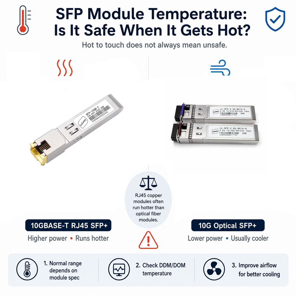
LuLeey’s guide to SFP module temperature explains why touch temperature is not an acceptance test and why the internal reading must be compared with the specified range.
The DDM display can be wrong or incomplete
The host must correctly interpret the module’s calibration method, scaling, units, thresholds and status flags. A module can be detected and still have unreliable telemetry in that host.
Nokia’s DDM documentation notes that DDM availability depends on the transceiver and that displayed information from non-Nokia modules is not guaranteed for formatting or accuracy. This is vendor-specific guidance, but it illustrates a general troubleshooting rule: confirm an unusual reading with a documented host-module combination.
Suspect interpretation trouble when:
- The displayed current is impossible or fixed at one extreme.
- The threshold units do not match the live-value units.
- A firmware update changed the reading without any physical change.
- The same module reports very different values in two supported hosts.
- DDM support is not indicated correctly in the module EEPROM.
- Temperature, voltage, TX power or RX power is also clearly nonsensical.
Do not edit alarm thresholds merely to hide a doubtful value. First establish whether the value or the alarm interpretation is wrong.
Read TX Bias with Four Companion Measurements
1. Temperature
Record the module temperature at the same moment as the bias current. A current that follows temperature and stabilizes can be normal for that design. A current that continues climbing at stable temperature is a different pattern.
2. TX output power
TX power is the most important companion value. Compare it with the module’s specified transmitter range and with its own earlier readings.
Useful patterns include:
- Bias up, TX power stable: the control loop may still be maintaining output.
- Bias up, TX power down: possible degradation, transmitter fault or bad telemetry.
- Bias high, TX power high: check both thresholds and receiver-overload risk at the far end.
- TX power invalid while TX is disabled: do not diagnose the laser from a disabled-state reading.
SFF-8472 states that the reported TX power is normally based on a laser monitor photodiode and is invalid when the transmitter is disabled.
3. Supply voltage
An abnormal module supply can disturb transmitter operation or DDM conversion. Compare voltage with the module-programmed thresholds and the host specification.
If several optics in the same device show voltage anomalies together, investigate the host, power and thermal environment before declaring several lasers bad at once.
4. Remote RX power and errors
Check what the far-end transceiver receives from the suspect transmitter. Also record interface errors, forward-error-correction counters where applicable, loss-of-signal, link flaps and traffic impact.
The useful comparison is:
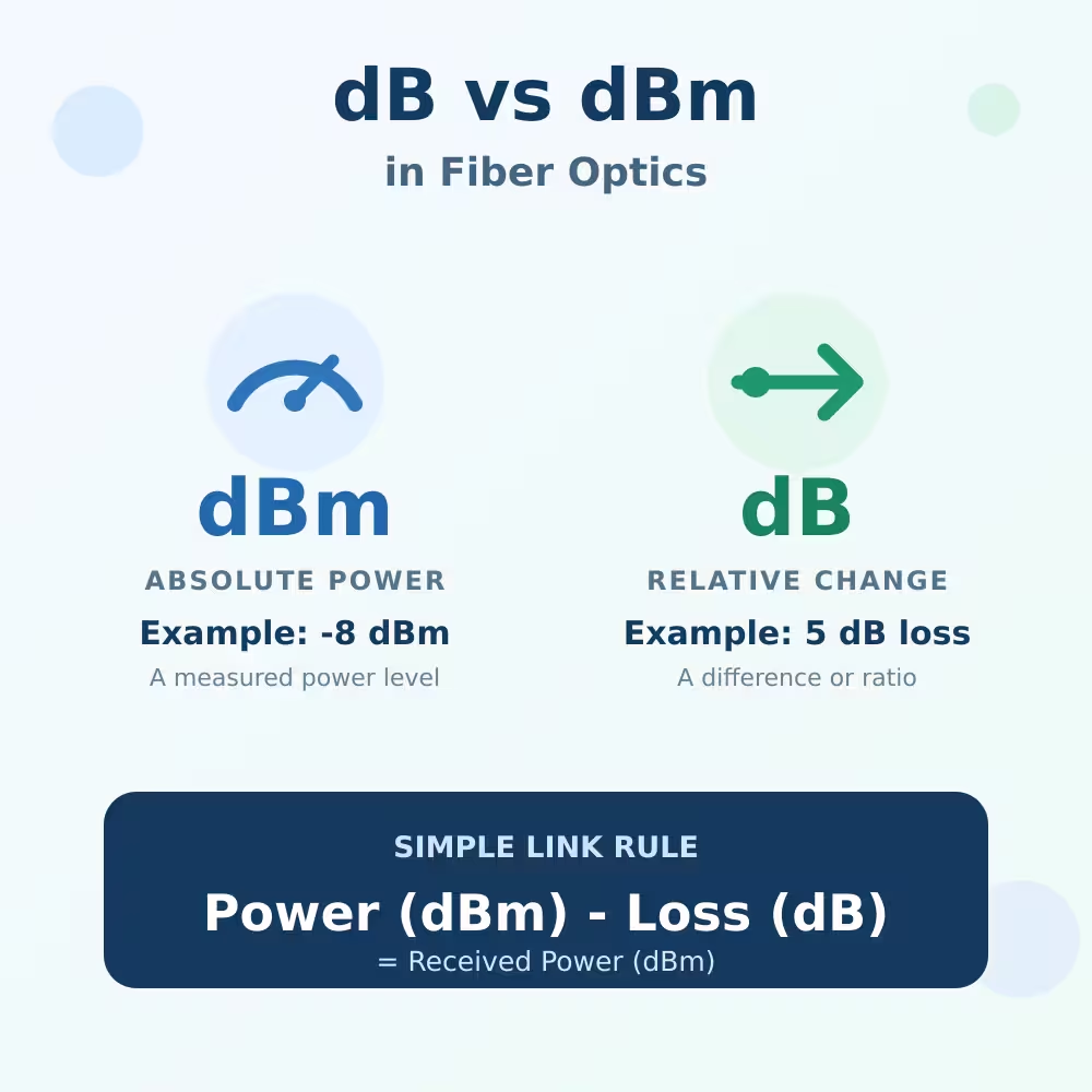
Approximate path loss = local TX power − remote RX power
This is a field estimate, not a substitute for calibrated insertion-loss testing. DDM uncertainties at both ends contribute to the difference.
If local TX power remains steady but remote RX power falls, the fiber path, connector interfaces or remote receiver are stronger suspects than local Laser Bias alone.
Does a Dirty Fiber Connector Cause High TX Bias?
Usually not in the way users imagine.
A dirty connector, bend, splice loss or damaged fiber reduces the optical power reaching the remote receiver. A normal Ethernet SFP does not receive a continuous instruction from the far end to increase its laser current until the remote RX value improves. Its local transmitter control loop uses internal information, including its monitor photodiode, rather than ordinary far-end path-loss feedback.
Therefore:
- Dirty fiber can cause low remote RX power, errors and link loss.
- Dirty fiber does not automatically explain a local TX Bias High flag.
- A link can have both a high-bias transmitter and a dirty path, but each needs its own evidence.
Inspect and clean connectors when RX power or measured path loss points to contamination. Do not disconnect a stable production link solely because the local bias number is high.

A Seven-Step Troubleshooting Workflow
Step 1: Capture the complete evidence
Save the module vendor, part number, serial number, date code, host model, port, firmware and timestamp. Capture all DDM readings, all four thresholds, flag states, TX fault, RX loss-of-signal and interface counters.
Do not copy only the bias value into a ticket. Without temperature and TX power, the most useful context is missing.
Step 2: Confirm DDM support and units
Verify that the module declares diagnostic monitoring, the host supports DDM on that port and the current is displayed in mA rather than raw counts or µA. Check whether the module uses internal or external calibration.
If the host shows thresholds, compare the live value with the module’s own high-warning and high-alarm values. Do not borrow a threshold from another model.
Step 3: Reread after the module stabilizes
Wait until the diagnostic data is valid and temperature has settled. Read the status again. A transient flag during insertion is different from a persistent warning under steady operation.
Use repeated readings at a meaningful interval. A single screenshot cannot show direction or rate of change.
Step 4: Build a short trend
Record bias, temperature, voltage and TX power together from cold start through normal load. If historical monitoring exists, compare days or months at similar temperatures.
Trend the same module, not a fleet-wide raw-current average across different part numbers.
Step 5: Correlate the far end
Capture the remote module’s RX power, loss-of-signal, errors and event timestamps. Compare the estimated path loss with a known-good baseline.
If remote RX changed while local TX did not, inspect the optical path. If local TX power and bias degrade together, concentrate on the transmitter and its operating environment.
Step 6: Swap one controlled variable
During an approved maintenance window, test one change at a time:
- Move the suspect module to another supported port, if the platform permits.
- Test a known-good, correctly coded module of the same application.
- Test the suspect module in a documented compatible host.
- Clean and retest the optical path only when path evidence supports it.
Never look into a fiber or transceiver port. Treat the connection as active and follow the network owner’s optical-safety and cleaning procedure.
Step 7: Validate service after the action
After reseating, cleaning, host testing or module replacement, confirm:
- Stable DDM readings after warm-up
- No warning or alarm that should have cleared
- TX and remote RX power within the exact module ranges
- No TX fault, RX loss-of-signal or rising error counters
- Stable link and expected traffic performance
- Monitoring and alerting restored
Keep the before-and-after data with the module serial number. It becomes the baseline for the next event.
When Should You Replace the Module?
Plan immediate or urgent replacement testing when any of these conditions is present:
- TX Bias High Alarm persists after a confirmed reread.
- TX fault, link loss or significant errors accompany the alarm.
- Bias continues to rise while TX output falls at comparable temperature.
- The module cannot maintain specified TX power.
- Voltage and temperature are within range, but a known-good identical application does not reproduce the problem.
- The manufacturer defines the flag as an end-of-life indication.
Plan monitored maintenance rather than an emergency swap when a warning is stable, TX power remains within specification, the link has no errors and the vendor supports continued operation. Set a review trigger based on trend, not an invented universal mA value.
Return or quarantine the module when diagnostics remain implausible in multiple supported hosts. A module that carries traffic but reports unusable telemetry can still undermine monitoring and fault isolation.
Applying the Method to LuLeey DDM Modules
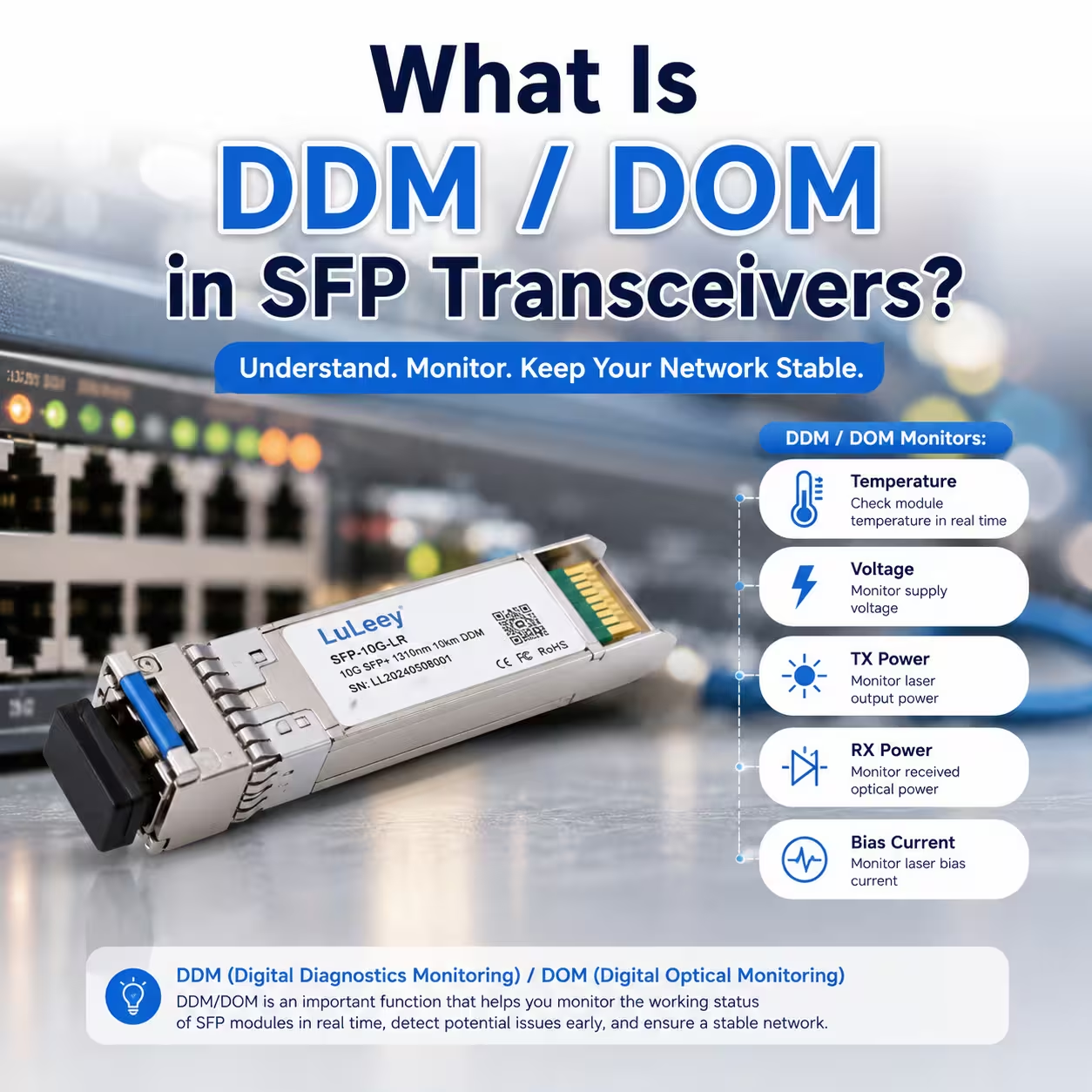
LuLeey’s DDM/DOM overview introduces the five SFP diagnostic quantities and already recommends interpreting bias as a trend together with TX power. This article extends that foundation into a specific alarm workflow.
The LL-SFP-10G-LR page lists DDM/DOM support, a 10.3125Gbps data rate, 1310nm transmission, duplex LC, single-mode fiber, a 10km reach and a 0–70°C operating range. It also lists TX power from −5 to +0.5dBm and receiver sensitivity below −13dBm.
The LL-SFP-10G-BX10 page lists 10Gbps, up to 10km over single-mode fiber, an LC simplex interface, a 1270nm TX/1330nm RX configuration and DDM support.
These pages confirm that the listed modules support diagnostics; they do not publish a universal TX-bias operating current or all four bias thresholds. Before approving an alarm response, provide LuLeey with:
- Exact part number, coding option, serial number and date code
- Host model, port, firmware and operating system or driver
- Current bias value and the module-reported warning/alarm thresholds
- Temperature, voltage, TX power and RX power from the same snapshot
- Remote RX power and interface-error history
- Cold-start and steady-state trend
- Whether the warning follows the module or stays with the host port
That evidence lets support distinguish an optical-transmitter problem from a thermal, host-interpretation or fiber-path issue without treating every high current value as the same fault.
Final Answer
A high SFP TX bias current means the module reports more laser-drive current than its manufacturer-programmed warning or alarm threshold. It can be an early degradation indicator, particularly when the module is trying to maintain constant optical power, but it is not a stand-alone failure verdict.
Use this order:
- Capture the complete DDM snapshot and the module’s own thresholds.
- Confirm the warning or alarm with a repeat read after valid data is available.
- Compare bias with temperature, voltage and TX output power.
- Compare local TX with far-end RX, errors and link events.
- Trend the same module under comparable conditions.
- Verify the reading in a supported host-module combination.
- Swap one variable during an approved maintenance window and validate service.
If bias rises while TX power falls, or an alarm accompanies TX fault and errors, prepare a replacement quickly. If TX power is stable and the link is clean, collect a trend and confirm the vendor’s thresholds before replacing a working module.
 SFP/SFP+ (1G/2.5G/5G/10G)
 SFP-T (1G/2.5G/10G)
 AOC Cable 10G/25G/40G/100G
 DAC Cable 10G/25G/40G/100G
 QSFP28 QSFP+ SFP28 100G/40G/25G
 Copper to Fiber Media Converters
 Fiber Media Converter PCBA Board
 OEO Fiber Media Converters
 Serial to Fiber Media Converters
 Video to Fiber Media Converters
 1000M GPON/EPON ONU
 10G EPON ONU/XG-PON/XGS-PON
 2.5G GPON/XPON STICK SFP ONU
 POE GPON/EPON ONU
 Wireless GPON/EPON ONT
 EPON OLT
 GPON OLT
 SFP PON Module
 Industrial Switches
 Managed Switches
 POE Switches
 Unmanaged Switches
 MTP/MPO Fiber Cables
 Fiber Optic Cassettes
 Fiber Optic Loopback
 Optic Cables and Fiber Pigtails
 Optical Splitters and Splitter Box
 Fiber Flange Connectors
 Optical Adapters
 Optical Attenuator
 Quick Connector and Connector Panel
 CATV Amplifier
 CATV Optical Receiver
 Visual Fault Locator
 OTDR
OTDR Optical Power Meter
 Fiber Optic Identifier
 Fiber Optic Cleaners
 Fiber Cleavers & Fiber Strippers
 Copper Tools


