Customs duties are the responsibility of customers, but standard logistics support DDP to most countries, duty-free such as US, DE, UK, CA, FR, IT, PL, AT, JP…





















































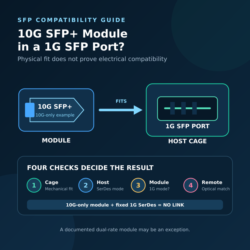
A 10G SFP+ in a 25G SFP28 port can work, but only when that exact host port supports a 10GbE electrical mode and accepts the module. The shared form factor lets the module fit. It does not force a 25G-only SerDes lane to operate at 10G.
If the host documentation lists both 10G and 25G for the port, the normal result is a 10G link after the correct port mode is selected. The module does not become a 25G module, and the usable path remains limited by the 10G link and the rest of the system.
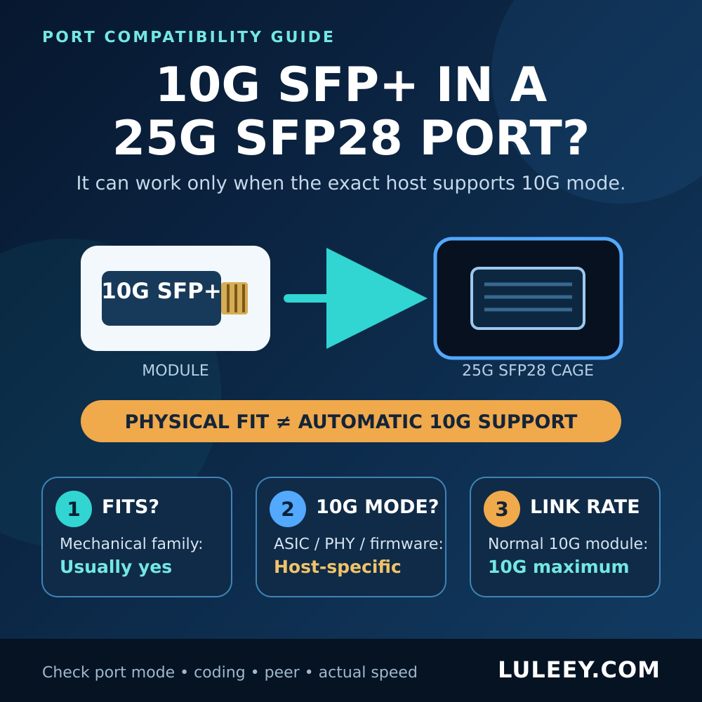
10G SFP+ in a 25G SFP28 Port: The Short Answer
| What you observe | What it proves | What still needs verification |
|---|---|---|
| The SFP+ module fits in the SFP28 cage | The mechanical format is compatible | Host 10G SerDes mode, power, coding and software support |
| The host reads the module identity | Presence and at least part of the management interface work | The high-speed link can run at 10G |
| The port documentation lists 10G/25G | The platform is designed for both rates under stated conditions | Exact module, firmware, port setting and peer |
| The interface reports Link Up at 10G | Both ends established the reported 10G link mode | Clean traffic, expected throughput and long-term stability |
| A 10G module is at one end and a 25G module at the other | Only the two installed module types are known | They will not form a normal link unless both ends use a matching rate and PMD |
The SNIA SFF-8402 specification places SFP10 and SFP28 in a common family for physical, low-speed electrical and management interfaces. The same specification says that other standards define performance at the different data rates. That is the practical boundary: a common cage and management framework do not guarantee that a particular host ASIC or PHY implements every line rate.
The IEEE 802.3by task-force record documents the approval of 25GbE work. A 25GbE physical layer and a 10GbE physical layer remain different operating modes even when they use modules with a similar external shape.
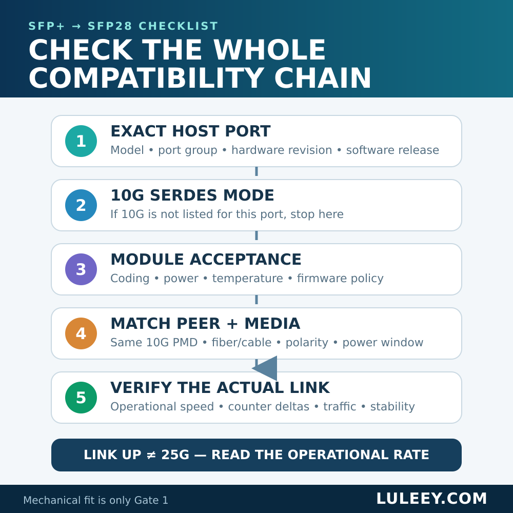
Check Six Compatibility Layers
1. Mechanical fit
SFP+ and SFP28 belong to the same compact, single-lane pluggable family. A normal SFP+ module can physically enter a compatible SFP28 cage.
Mechanical fit is only the first gate. It says nothing about the host’s supported SerDes rates, the port’s power and thermal limits, module coding, or whether the operating system will enable the module.
2. Host ASIC, PHY and SerDes mode
The decisive question is whether the exact switch or NIC port can drive and receive a 10G electrical signal. Some SFP28 ports are explicitly multi-rate. Others are fixed at 25G, or their lower-rate support depends on a specific port group, breakout profile, line card, firmware or driver.
Check the exact model, hardware revision and port number. A product family may contain several ASICs or port types, so a statement about one model or port block should not be applied to another.
3. Module identity, coding, power and temperature
A host may detect the module yet reject it because of its EEPROM coding, power requirement, thermal class or support policy. Record the complete module part number and revision rather than relying on “10G SFP+” printed on a sales page.
If the module is not detected, solve the presence and management-interface problem before troubleshooting the fiber. If the host reads the part number but reports an unsupported module, detection has succeeded; the next checks are host policy, coding, power, firmware and port mode.
4. Port rate, auto-negotiation and FEC
Do not assume that inserting a 10G module automatically changes the port speed. Some hosts infer the intended mode from the module. Some require a manual 10G setting. Others do not offer 10G on that port at all.
Follow the host documentation for speed, auto-negotiation and FEC in the selected 10G mode. A 25G FEC setting does not convert a 10G module into a 25G device. Save the original configuration and change one setting at a time so the result is interpretable.
5. Remote end, PMD and media
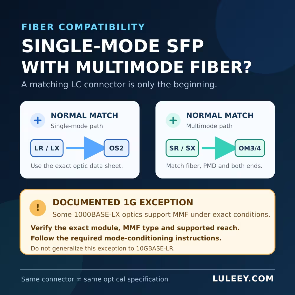
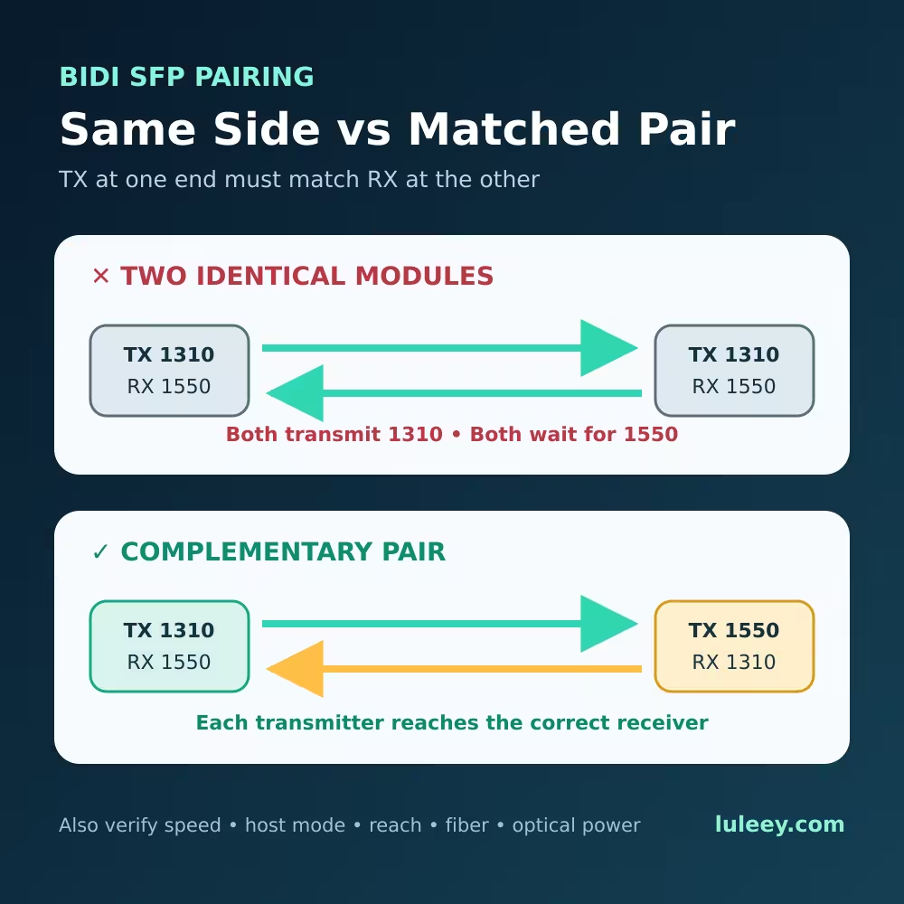
Both ends must use compatible 10GbE physical-medium specifications. For an optical link, verify the same rate and PMD, the correct single-mode or multimode fiber, connector polish, duplex polarity or BiDi pairing, wavelength plan, and the transmitter-to-receiver power window in each direction.
A 10GBASE-SR module at one end and a 25GBASE-SR module at the other are not a matching pair merely because both use 850 nm and an LC connector. Configure supported ports for the same rate and install modules or cable assemblies specified for that rate at both ends.
For a DAC or AOC, confirm that the complete cable assembly is supported at 10G by both hosts. For an RJ45 SFP+ module, separate the host-side electrical mode from the copper-side negotiated rate. A module can perform rate matching only when its chipset and firmware are designed for it. LuLeey’s 10G SFP+ to 2.5G RJ45 guide explains that two-sided check.
6. Actual link rate and usable throughput
After the link comes up, read the actual operating rate from both endpoints. A 25G label on the cage is the port’s maximum or supported capability, not evidence that the current session is running at 25G.
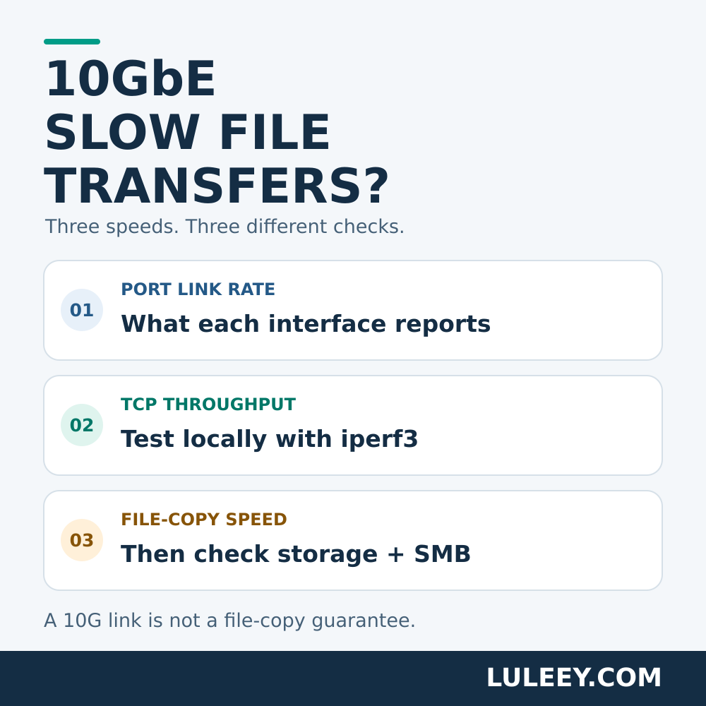
A link reported as 10G is limited to 10G-class line operation. Application throughput will be lower after Ethernet framing, protocol overhead, storage performance, CPU limits and traffic conditions. Verify counter deltas and traffic instead of judging from Link Up alone.
Does a 25G Port Automatically Negotiate Down to 10G?
There is no universal answer. Optical Ethernet ports do not all behave like multi-gigabit RJ45 ports. The host may select the rate from configuration, module information or a platform-specific process. The exact transceiver may also affect which options the host exposes.
Use this order:
- Find the speed list for the exact port in the current software release.
- Confirm that 10GbE is supported with the intended module or cable type.
- Check whether 10G must be configured manually.
- Apply only the documented 10G mode and its required FEC or negotiation setting.
- Confirm the peer is also set for a matching 10G PMD.
- Read the resulting operational speed at both ends.
If 10G is absent from the port’s supported-speed list, stop. A module recode, different fiber or forced 10G command cannot add a missing SerDes mode to the host hardware.
A Safe Test Before Production Deployment
Use a maintenance window or a lab port with the same hardware and software as production.
- Record the baseline. Save the host model, port, ASIC or PHY when known, firmware/driver, current speed, FEC, module policy and event log.
- Identify the module. Record part number, revision, coding, power, temperature rating and optical PMD or cable type.
- Confirm 10G host support. Use the exact port table and software release, not a general statement that SFP28 is backward compatible.
- Match the peer and media. Use a 10G module or cable specification at both ends and verify the optical path in both directions.
- Select the documented mode. Set 10G only if the host supports it. Avoid changing speed, FEC and several other variables together.
- Check status. Confirm module presence, accepted coding, Link Up, operational rate and any alarms.
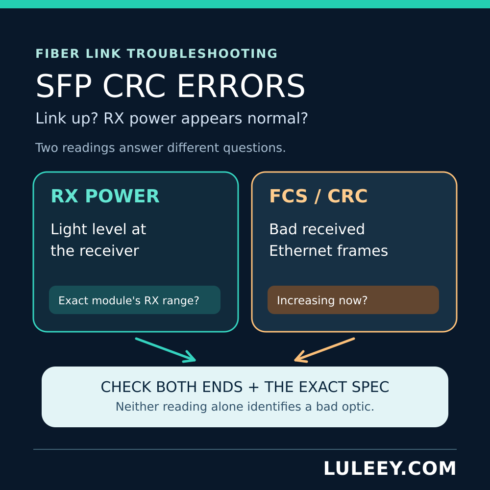
- Validate traffic. Compare timed counter deltas, look for FCS/CRC errors or link events, and run an authorized throughput test.
| Test result | Most useful next check |
|---|---|
| Module is absent | Seating, cage contacts, port power, driver and presence sensing |
| Identity is visible, but module is rejected | Coding, host policy, firmware, power and thermal limits |
| Module is accepted, but link stays down | 10G port mode, peer rate/PMD, FEC, fiber or cable, polarity and power |
| Link comes up at 10G | This is the expected ceiling for a normal 10G module; validate traffic |
| Link comes up but errors rise | Check both directions, media, optical power, contamination and host settings |
Do not use a successful test in one port as a universal compatibility certificate. Another port group, NIC revision or software release may expose different SerDes modes or module policies.
A Note About PON ONU Sticks
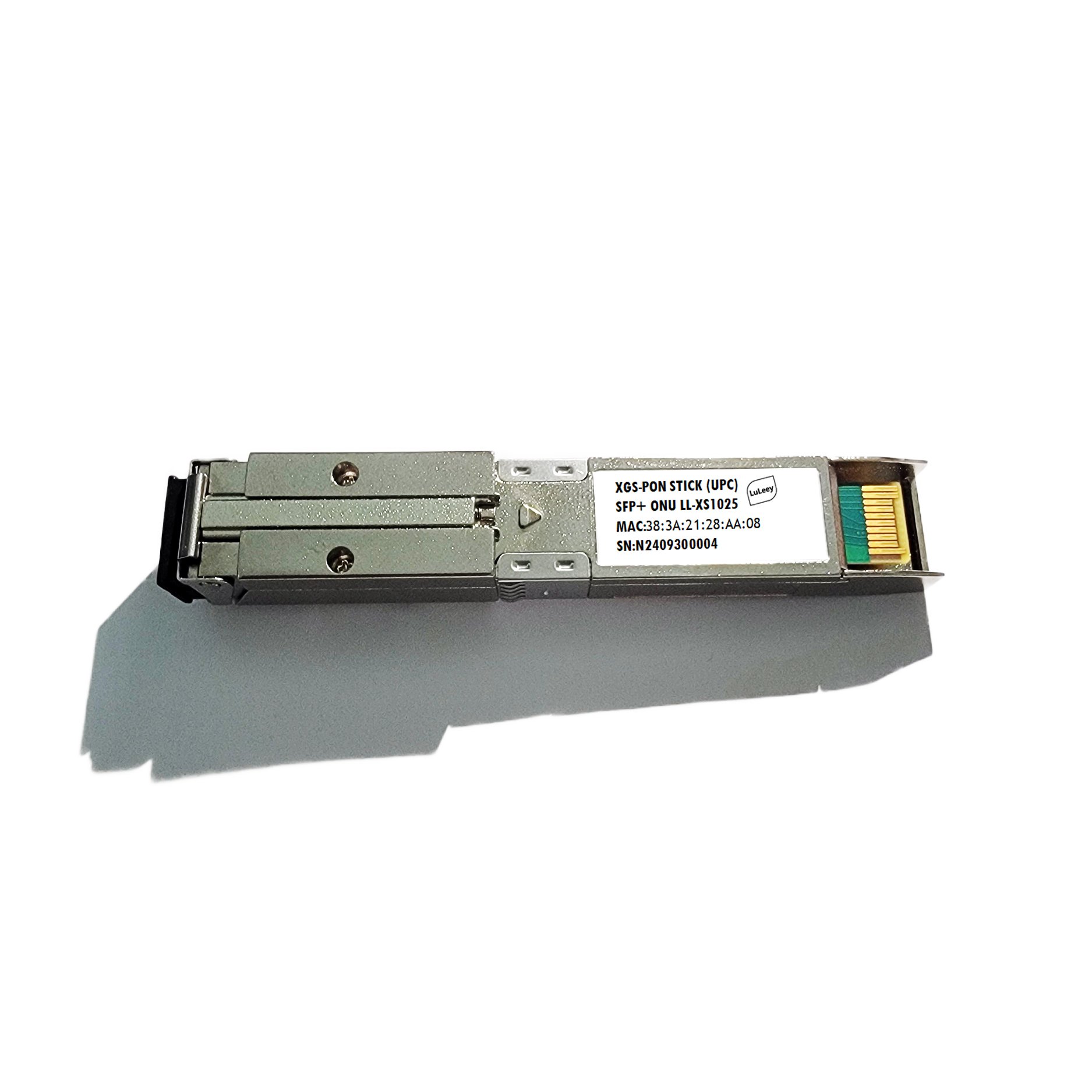
This guide concerns ordinary Ethernet optics and cable assemblies. A PON ONU Stick contains ONU logic and adds PON registration, authorization and service configuration to the host-interface question.
A 2.5G PON ONU Stick may work through a 1G or 10G SFP+ host at 1G only when both the Stick and host support a compatible 1G mode. Some SFP+ or SFP28 hosts may support a 2.5G Stick only with the right chipset or PHY, firmware or driver, port setting, module coding and Stick host mode. Physical fit, module detection, PON state, actual host rate and usable throughput must be checked separately.
Choosing a LuLeey 10G Module for a Multi-Rate Port
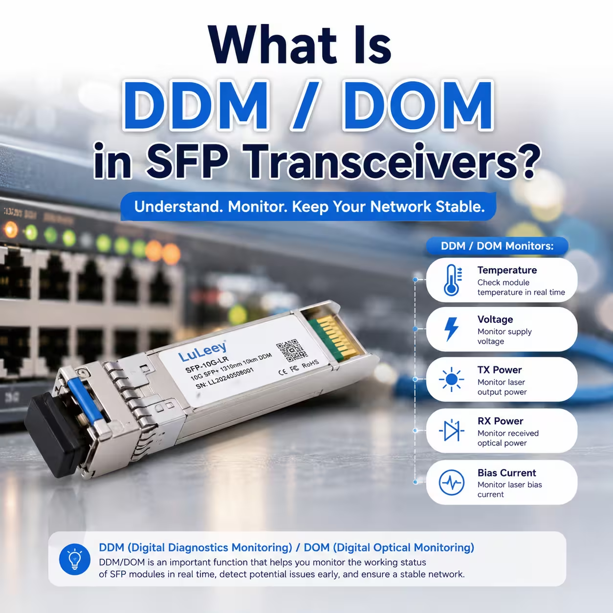
LuLeey’s SFP-10G-SR page lists an 850 nm, duplex-LC multimode module and up to 300 m on OM3/OM4 fiber. The LL-SFP-10G-LR page lists 10.3125 Gbps, 1310 nm, dual-LC, single-mode operation and 10 km reach, with DDM/DOM.
Neither product-page description proves that an unknown SFP28 host supports 10G mode. Select the optical PMD and fiber first, then confirm the exact host, port, firmware and coding. Distance labels also do not replace an optical-budget check for the real route.
The LuLeey optical transceiver range provides 10G and 25G product paths. Choose the rate from the endpoint capability and intended link, not from the cage shape alone.

 SFP/SFP+ (1G/2.5G/5G/10G)
 SFP-T (1G/2.5G/10G)
 AOC Cable 10G/25G/40G/100G
 DAC Cable 10G/25G/40G/100G
 QSFP28 QSFP+ SFP28 100G/40G/25G
 Copper to Fiber Media Converters
 Fiber Media Converter PCBA Board
 OEO Fiber Media Converters
 Serial to Fiber Media Converters
 Video to Fiber Media Converters
 1000M GPON/EPON ONU
 10G EPON ONU/XG-PON/XGS-PON
 2.5G GPON/XPON STICK SFP ONU
 POE GPON/EPON ONU
 Wireless GPON/EPON ONT
 EPON OLT
 GPON OLT
 SFP PON Module
 Industrial Switches
 Managed Switches
 POE Switches
 Unmanaged Switches
 MTP/MPO Fiber Cables
 Fiber Optic Cassettes
 Fiber Optic Loopback
 Optic Cables and Fiber Pigtails
 Optical Splitters and Splitter Box
 Fiber Flange Connectors
 Optical Adapters
 Optical Attenuator
 Quick Connector and Connector Panel
 CATV Amplifier
 CATV Optical Receiver
 Visual Fault Locator
 OTDR
OTDR Optical Power Meter
 Fiber Optic Identifier
 Fiber Optic Cleaners
 Fiber Cleavers & Fiber Strippers
 Copper Tools


