Customs duties are the responsibility of customers, but standard logistics support DDP to most countries, duty-free such as US, DE, UK, CA, FR, IT, PL, AT, JP…





















































This LL-L2+MES-425GE2SFP+ User Guide explains how to access the switch Web Management interface and complete the most common initial settings.
6 Port 2.5G L2+ Managed Ethernet SwitchThe LL-L2+MES-425GE2SFP+ is a compact L2+ managed Ethernet switch with:
- 4 × 10/100/1000/2500Mbps RJ45 ports
- 2 × 10G SFP+ uplink ports
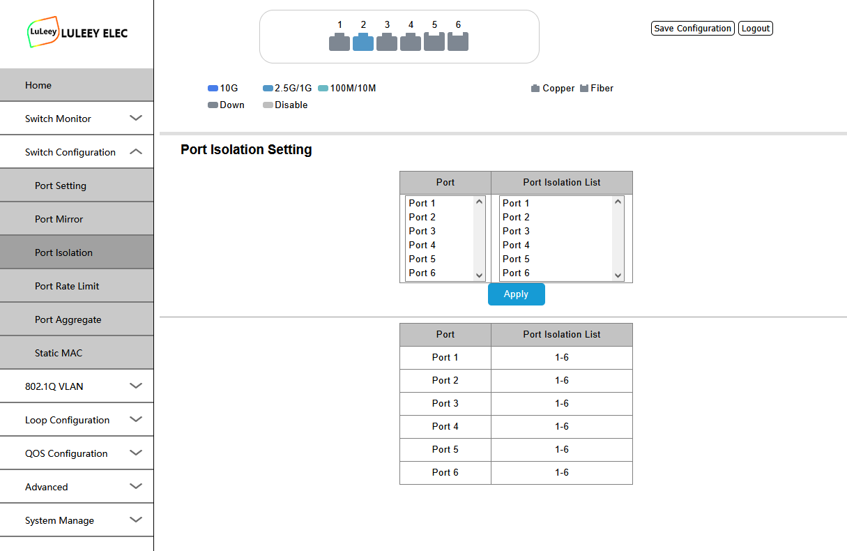
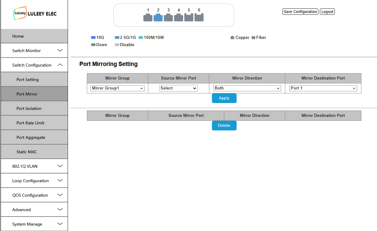
- Web Management
- vlan
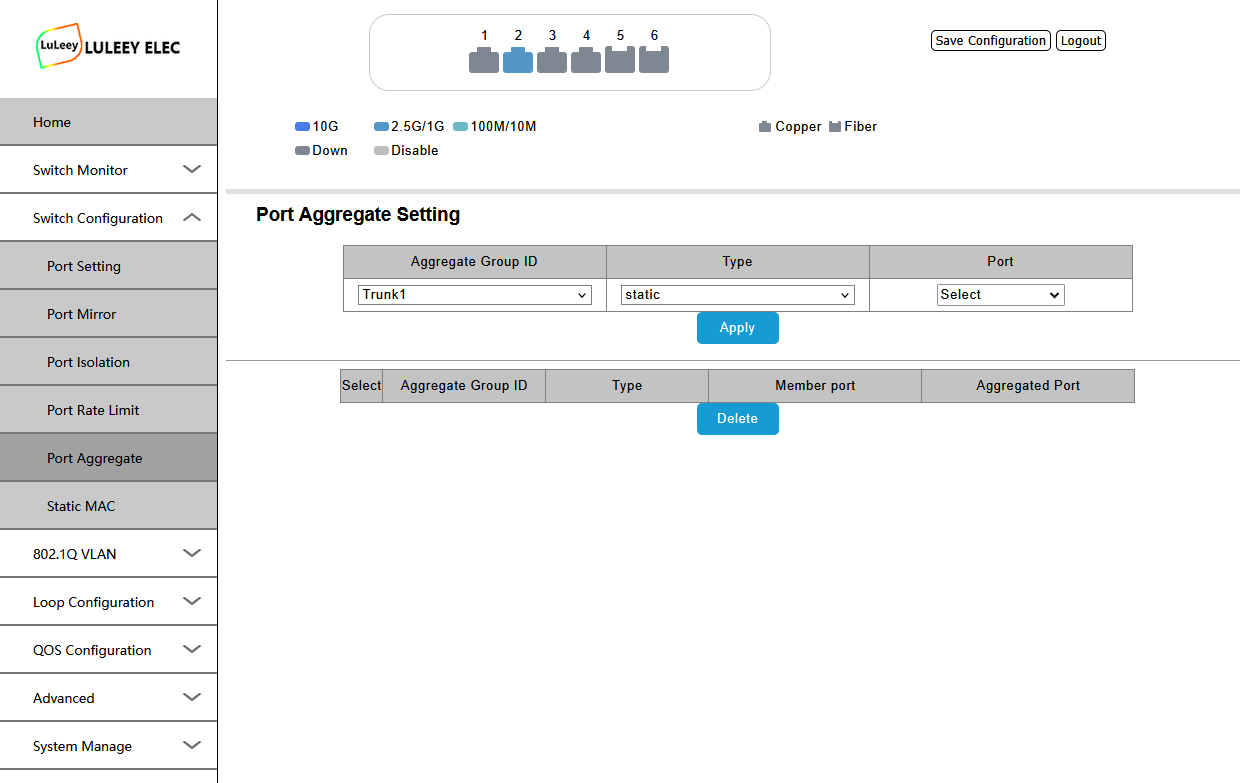
- Link Aggregation
- Loop Detection
- 60Gbps switching capacity
This guide is intended for initial setup and basic network configuration.






1. Connect Your PC to the Switch
Connect your computer directly to one of the RJ45 Ethernet ports on the switch.
Before opening the Web Management page, configure your computer with an IP address in the same subnet as the switch.
Default Switch IP
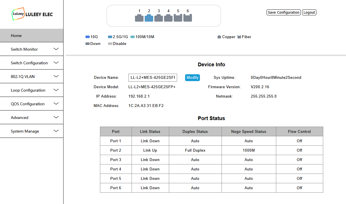
Switch IP: 192.168.2.1
Configure your computer with an address such as:
| Setting | Example |
|---|---|
| IP Address | 192.168.2.100 |
| Subnet Mask | 255.255.255.0 |
| Default Gateway | Leave blank or use 192.168.2.1 |
Do not use 192.168.2.1 on your computer because this address is already used by the switch.
2. Check the Connection
Before opening the Web UI, you can test connectivity from your computer.
On Windows, open Command Prompt and enter:
ping 192.168.2.1
If you receive replies from 192.168.2.1, your computer and the switch are communicating correctly.
If there is no reply, check:
- Ethernet cable connection
- Link LED status
- PC IP address
- Subnet mask
- Whether another device is already using 192.168.2.1
3. Login to the Web Management Interface
Open a web browser and enter:
http://192.168.2.1
The switch login page should appear.
Default Login
Username: admin
Password: admin
If the default credentials do not work, check the label, supplied documentation or configuration information included with your switch.
After logging in, you can access the switch management interface.
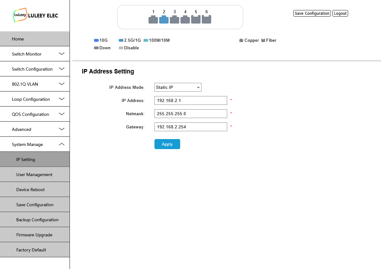
4. Change the Switch Management IP
If your existing router or LAN also uses the 192.168.2.x network, you may want to assign the switch a different management IP.
For example, if your router uses:
192.168.1.1
you can configure the switch as:
192.168.1.20
Use an unused IP address in your existing LAN.
After changing the management IP, reconnect to the switch using the new address.
Important
Before changing the IP address, make sure that:
- The new IP is in the correct subnet.
- The address is not already used by another device.
- You record the new management IP.
Otherwise, you may temporarily lose access to the Web Management interface.
5. RJ45 Port Configuration
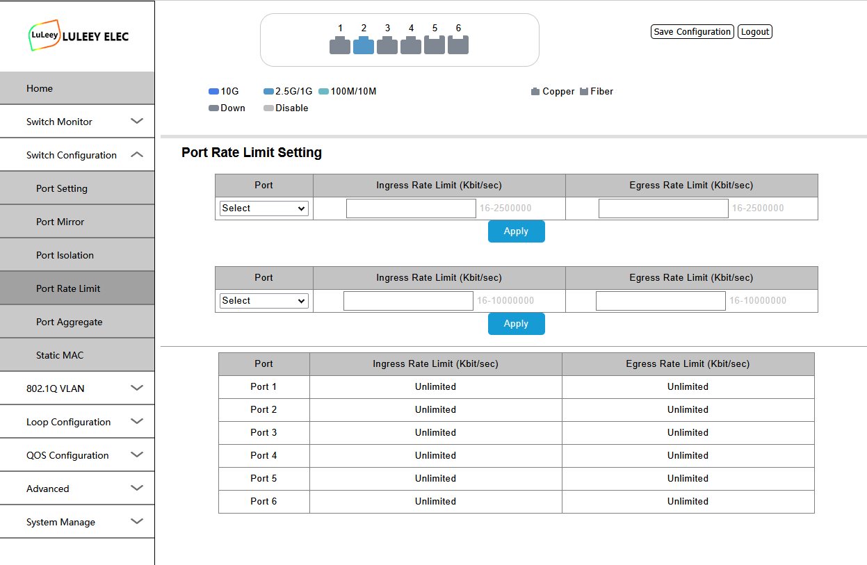
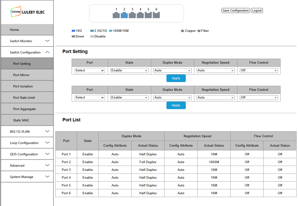
The four RJ45 ports support Ethernet auto-negotiation up to 2.5Gbps.
Supported speeds include:
- 10Mbps
- 100Mbps
- 1Gbps
- 2.5Gbps
For normal use, leave speed and duplex settings on Auto Negotiation unless you have a specific reason to configure them manually.
The actual negotiated speed depends on:
- Connected device
- Ethernet cable
- NIC capability
- Port configuration
For 2.5Gbps connections, Cat5e may work over suitable distances and cable quality, while Cat6 or better is generally preferable for new installations.
6. 10G SFP+ Port Setup
The switch provides two SFP+ uplink ports for high-speed connections.
Typical applications include:
- NAS
- Server
- Router
- Another Ethernet switch
- 10G network card
- Fiber uplink
Depending on the connected equipment, you can use compatible:
- SFP+ optical transceivers
- DAC cables
- AOC cables
Always make sure the transceiver, fiber type, wavelength and device on the opposite side are compatible.
If an SFP+ link does not come up, check the module compatibility and link parameters before assuming that the switch port is faulty.
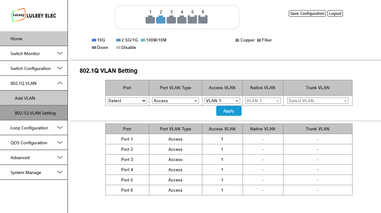
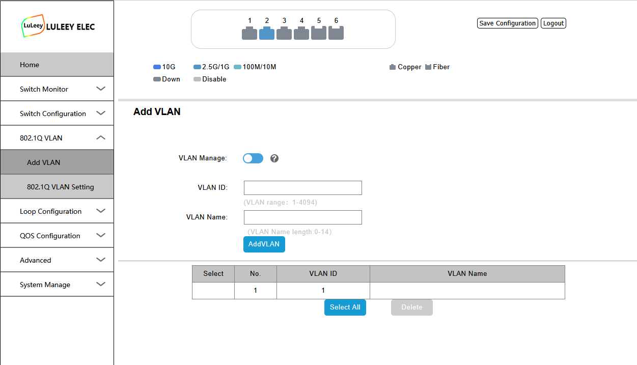
7. VLAN Configuration
VLANs allow you to separate devices into different logical networks while using the same physical switch.
Common examples include separating:
- Home network
- Servers
- IoT devices
- CCTV cameras
- Guest Wi-Fi
Before changing VLAN settings, determine which ports should be:
- Untagged/access ports
- Tagged/trunk ports
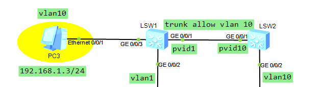
A simple example:
| Port | Device | VLAN |
|---|---|---|
| Port 1 | PC | VLAN 10 |
| Port 2 | NAS | VLAN 10 |
| Port 3 | IoT device | VLAN 20 |
| SFP+ Port | Router / Main Switch | VLAN 10 + VLAN 20 Tagged |
When configuring VLANs remotely, avoid removing the management port from the VLAN you are currently using. Otherwise, you may lose access to the switch.
8. Link Aggregation
Link Aggregation allows multiple physical Ethernet links to be grouped into one logical connection.
It can be useful when connecting devices such as:
- NAS
- Server
- Main switch
The connected device must also support the same aggregation method.
Do not simply connect two cables between two switches without configuring aggregation or a loop-prevention protocol. This may create a network loop.
Also remember that link aggregation does not normally make one individual TCP connection twice as fast. Its main benefit is distributing multiple traffic flows across several links.
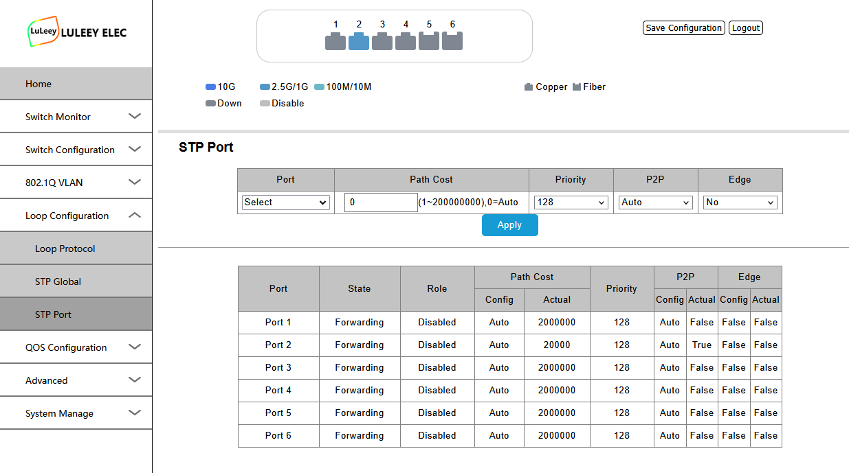
9. Loop Detection
A network loop can occur when Ethernet ports are accidentally connected in a way that creates multiple forwarding paths.
Typical symptoms include:
- Very high network traffic
- Network becoming extremely slow
- Devices disconnecting
- Switch LEDs flashing continuously
- Entire LAN becoming unstable
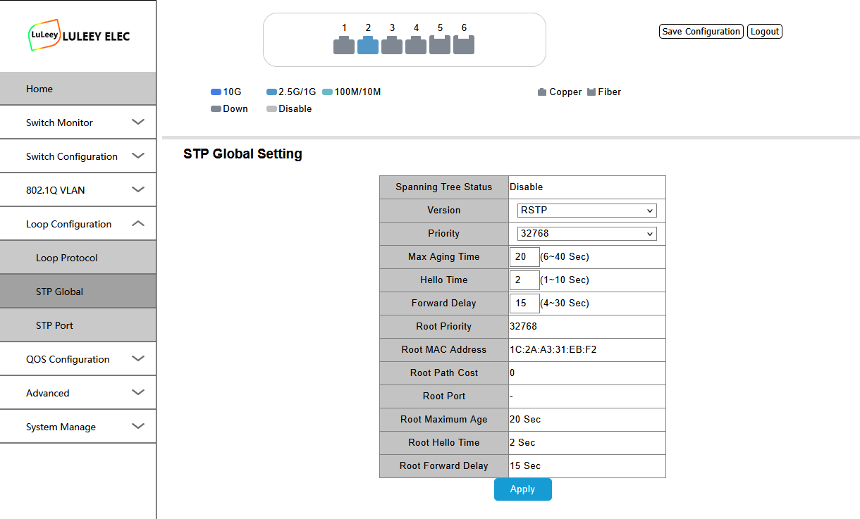
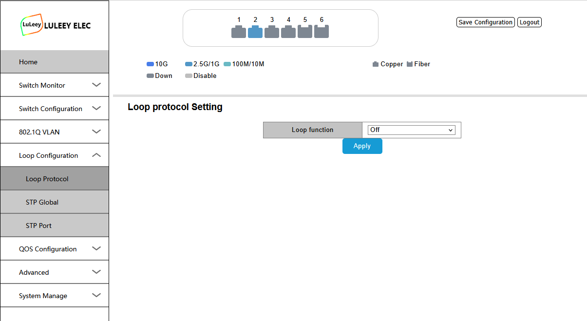
Enable the switch’s available loop detection or spanning-tree-related functions when your network topology requires redundant links.
For a simple home or small office network with only one path between switches, avoid unnecessary parallel connections.
10. Save the Configuration
After making changes in the Web Management interface, make sure the configuration is saved.
Some managed switches distinguish between:
- Current running configuration
- Saved startup configuration
If changes are not saved correctly, the switch may return to the previous configuration after a reboot.
After configuring important settings such as VLANs or management IP, restart the switch once and confirm that the settings remain active.
Troubleshooting
I Cannot Open 192.168.2.1
Check that your computer is using an address such as:
192.168.2.100 / 255.255.255.0
Then try:
ping 192.168.2.1
Temporarily disable Wi-Fi if your computer is using another network at the same time.
The Login Page Opens but admin/admin Does Not Work
Check whether the password has previously been changed.
If the device has been configured before, the current login credentials may no longer be the factory defaults.
2.5G Port Only Negotiates at 1G
Check:
- Whether both devices support 2.5GbE.
- Ethernet cable quality.
- Port speed settings.
- NIC driver and configuration.
The final Ethernet speed is determined by both ends of the connection.
SFP+ Port Has No Link
Check:
- SFP+ module or DAC compatibility.
- Fiber TX/RX connection.
- Optical wavelength pairing.
- Remote device port configuration.
- Whether both ends support the selected speed.
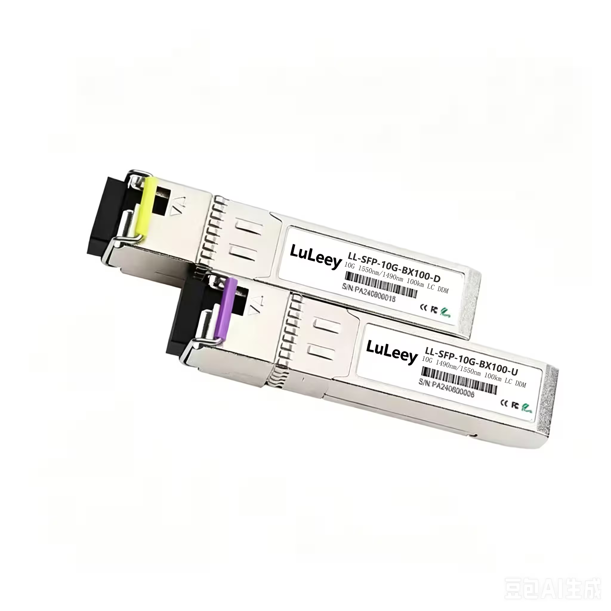
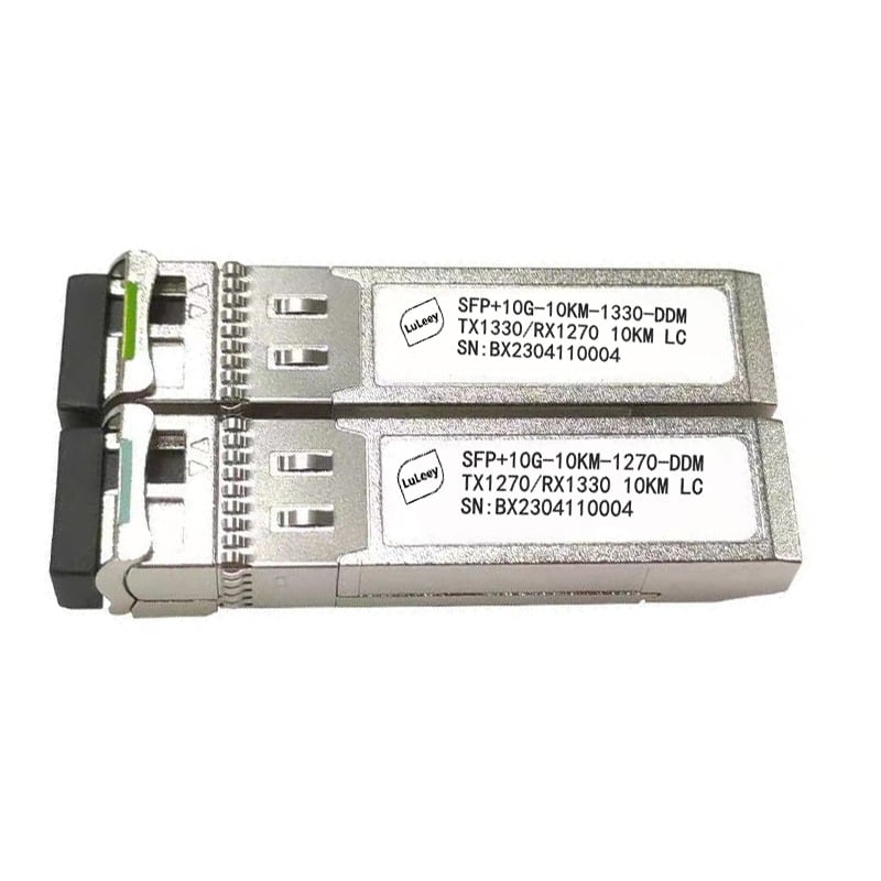
For BiDi transceivers, the two modules must use complementary TX and RX wavelengths.
Typical Network Example
A simple home lab configuration may look like:
Router → 10G SFP+ → LL-L2+MES-425GE2SFP+ → 2.5G PC / NAS / Wi-Fi AP
The two SFP+ ports can be used as high-speed uplinks while the four 2.5G RJ45 ports connect local Multi-Gigabit Ethernet devices.
For product specifications and available versions, see the 6 Port 2.5G L2+ Managed Ethernet Switch product page.
 SFP/SFP+ (1G/2.5G/5G/10G)
 SFP-T (1G/2.5G/10G)
 AOC Cable 10G/25G/40G/100G
 DAC Cable 10G/25G/40G/100G
 QSFP28 QSFP+ SFP28 100G/40G/25G
 Copper to Fiber Media Converters
 Fiber Media Converter PCBA Board
 OEO Fiber Media Converters
 Serial to Fiber Media Converters
 Video to Fiber Media Converters
 1000M GPON/EPON ONU
 10G EPON ONU/XG-PON/XGS-PON
 2.5G GPON/XPON STICK SFP ONU
 POE GPON/EPON ONU
 Wireless GPON/EPON ONT
 EPON OLT
 GPON OLT
 SFP PON Module
 Industrial Switches
 Managed Switches
 POE Switches
 Unmanaged Switches
 MTP/MPO Fiber Cables
 Fiber Optic Cassettes
 Fiber Optic Loopback
 Optic Cables and Fiber Pigtails
 Optical Splitters and Splitter Box
 Fiber Flange Connectors
 Optical Adapters
 Optical Attenuator
 Quick Connector and Connector Panel
 CATV Amplifier
 CATV Optical Receiver
 Visual Fault Locator
 OTDR
OTDR Optical Power Meter
 Fiber Optic Identifier
 Fiber Optic Cleaners
 Fiber Cleavers & Fiber Strippers
 Copper Tools


