Customs duties are the responsibility of customers, but standard logistics support DDP to most countries, duty-free such as US, DE, UK, CA, FR, IT, PL, AT, JP…





















































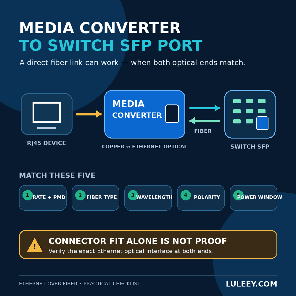
A media converter to switch SFP port link can work directly. In a standard Ethernet installation, the switch can be the optical peer, so you do not automatically need a second media converter at the far end.
However, an LC connector that fits is not proof of compatibility. Both ends must agree on the Ethernet optical interface, line rate, fiber type, wavelength direction, and acceptable optical power. The switch must also support the installed SFP and its host-side operating mode.
This guide gives you a practical way to decide before you connect the fiber—and a short test sequence if the link stays down.
Media Converter to Switch SFP Port: The Short Answer
The direct link should work when all of these conditions are true:
- Both optical ends use Ethernet, not two different protocols.
- Both ends use the same Ethernet line rate and compatible physical-medium specification, often called the PMD.
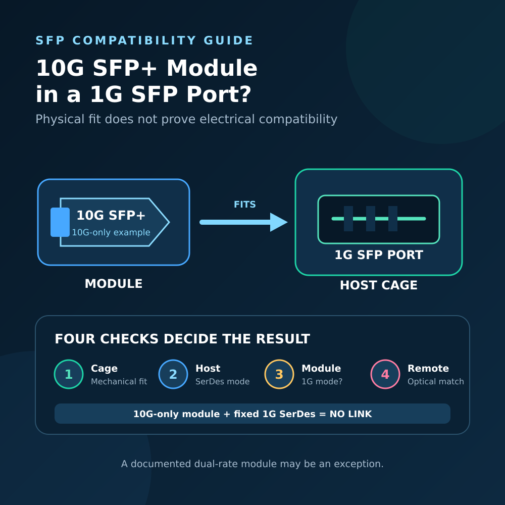
- Each host supports the SFP installed in its slot, including the required electrical SerDes mode, port speed, firmware behavior, and module coding.
- The fiber type, wavelength plan, connector polish, and Tx/Rx direction are correct.
- The received optical power falls between the receiver’s overload and sensitivity limits.
The IEEE 802.3 Ethernet standard defines speed-specific interfaces and multiple optical PHY types. That is why “both are Ethernet” or “both say SFP” is not a sufficient compatibility test. IEEE 802.3-2022
What Must Match on the Two Optical Ends?
Use the following table as a pre-installation worksheet.
| Check | Media converter side | Switch side | Why it matters |
|---|---|---|---|
| Protocol | Ethernet optical interface | Ethernet optical interface | A normal Ethernet SFP is not a GPON, EPON, or XGS-PON endpoint. |
| Line rate and PMD | For example, 1000BASE-SX or 1000BASE-LX | The same or explicitly interoperable specification | 1G and 10G optics do not create a common line rate by themselves. SX and LX are different optical specifications. |
| Host support | Converter supports the module’s rate and host interface | Switch port, ASIC/PHY, firmware, and configuration support the module | The SFP form factor only describes the package; it does not guarantee host compatibility. |
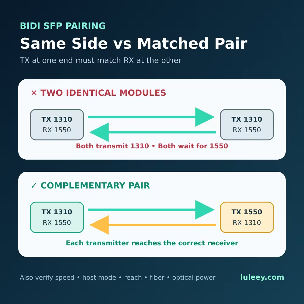
| Fiber and wavelength | Multimode or single-mode; duplex or BiDi | Matching fiber and wavelength plan | A duplex pair needs crossed Tx/Rx paths. A BiDi link needs a complementary wavelength pair. |
| Connector and polish | Correct connector and end-face type | Correct connector and end-face type | A mating adapter does not make an unsuitable polish or optical design safe. |
| Optical power | Transmit range and receiver limits | Transmit range and receiver limits | Too little power causes loss of signal; too much can overload a receiver. |
Do not use distance alone as the selection rule. A “20 km” label is a reach class, not a complete interoperability specification. Read the exact module datasheets at both ends.
Why SFP, SFP+, and SFP28 Labels Are Not Enough
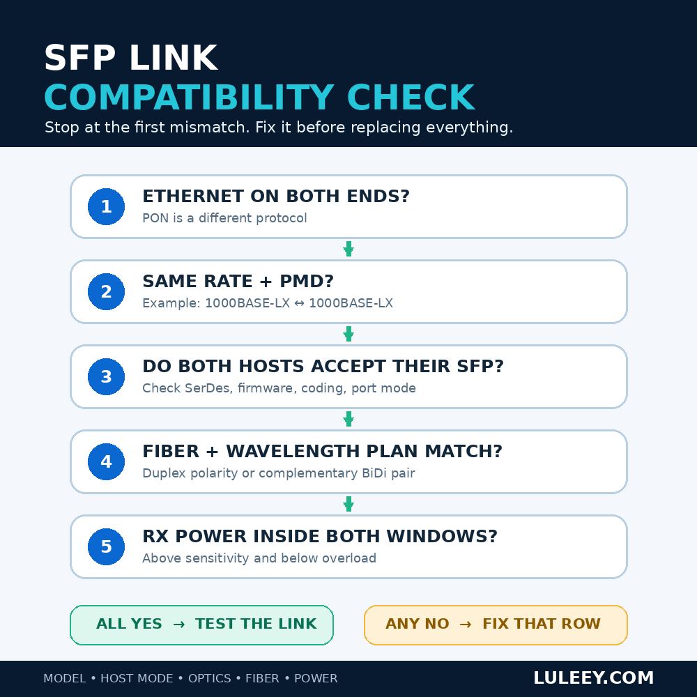
The cage is only the physical slot. A successful link depends on several separate layers:
- Physical fit: Does the module fit the cage?
- Host electrical mode: Can the switch PHY or SerDes operate in the mode required by that module?
- Port configuration: Does the port support the selected rate, and is the rate fixed or configurable?
- Optical line: Do the two modules transmit and receive a compatible signal?
- Actual throughput: What rate is available after the link is established and protocol overhead is considered?
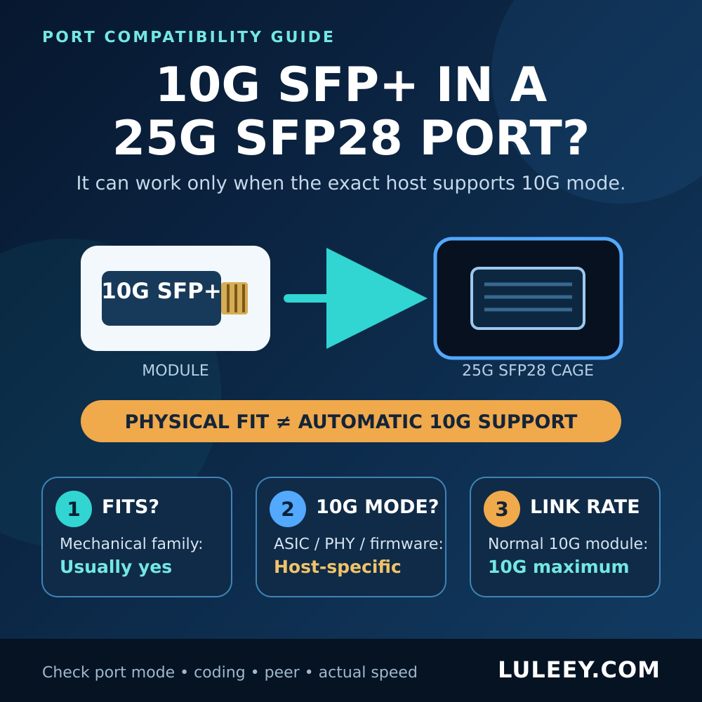
For example, a 1G SFP may work in some SFP+ switch ports when the port, PHY, firmware, and configuration explicitly support 1G operation. It will not become a 10G link, and a 10GBASE-LR SFP+ at one end will not normally link to a 1000BASE-LX SFP at the other.
The SFF-8472 specification defines SFP memory fields for items such as identifier, connector, interface codes, nominal signaling rate, reach, and wavelength. A host can use that information to identify or reject a module. Module detection still does not prove that the remote optic, fiber path, and power budget are correct. members.snia.org
Common Pairings: Likely to Work or Not?
| Pairing | Expected result | Condition |
|---|---|---|
| 1000BASE-LX converter or SFP ↔ 1000BASE-LX switch SFP | Usually workable | Both hosts support the modules; fiber, connectors, polarity, and power budget are correct. |
| 1000BASE-SX ↔ 1000BASE-LX | Do not treat as compatible | Both are Gigabit Ethernet, but their optical media specifications differ. |
| 1G converter ↔ 10GBASE-LR SFP+ | No normal link | The optical line rates and PMDs do not match. |
| Duplex optic ↔ single-fiber BiDi optic | No | The optical channel designs are different. |
| BiDi module ↔ identical fixed-wavelength BiDi module | Usually no | The pair normally needs complementary Tx/Rx wavelengths. |
| Standard Ethernet converter ↔ ordinary switch SFP, different brands | Potentially yes | Standards match and both hosts accept their local modules. |
| GPON/EPON/XGS-PON fiber ↔ ordinary Ethernet SFP | No | PON and point-to-point Ethernet use different protocols and optical behavior. |
A Concrete 1G Example
The LuLeey LL-SFPMC1000 product page specifies one 10/100/1000M RJ45 port and one 1000M SFP slot compatible with 1.25G SFP modules. luleey.com
For an ordinary Ethernet deployment, a practical design is:
Ethernet device → RJ45 cable → LL-SFPMC1000 → supported 1G Ethernet SFP → matching fiber → supported 1G Ethernet SFP in the switch
The RJ45 port can negotiate 10, 100, or 1000 Mb/s according to the product page, while the optical slot is specified as 1000M. Copper-side negotiation therefore does not turn the SFP side into a 10G interface.
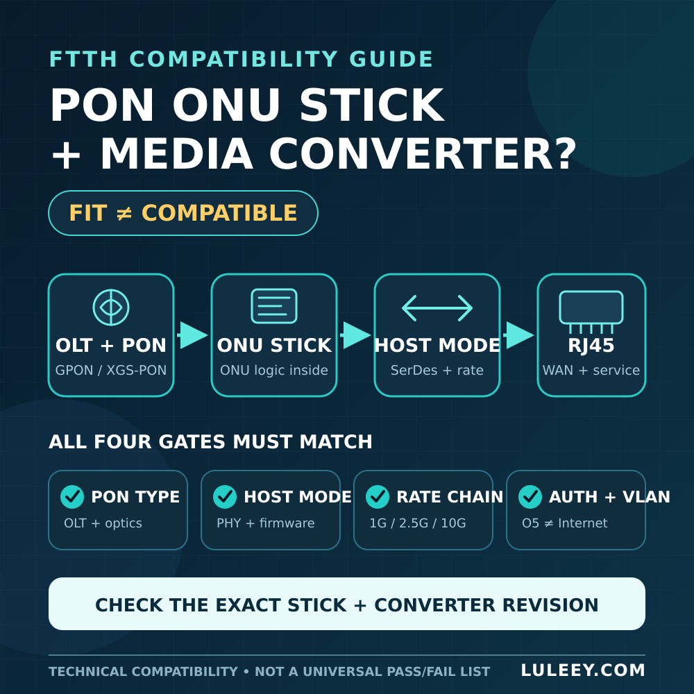
The same product page also describes special PON-stick use cases. Treat those as a separate host-compatibility problem. A 2.5G PON ONU Stick may fall back to a compatible 1G host mode when both the stick and host support it; some SFP+ hosts may also support 2.5G with suitable silicon and firmware.
Never decide from the SFP/SFP+ label alone. Verify the exact stick model, host chipset or PHY, firmware and driver, port settings, module coding, power budget, and the stick’s host mode.
Six Steps to Build and Test the Link
1. Record every exact model
Write down the media converter model, both optics, switch model, switch port, fiber type, and any adapters. Avoid working from color or connector shape alone.
2. Compare the optical specifications
Confirm the protocol, line rate, PMD, wavelength, fiber type, reach class, transmitter range, receiver sensitivity, and overload limit.
The Fiber Optic Association’s data-link reference explains the basic point-to-point model: the transmitter at one end must feed a compatible receiver at the other through the intended fiber type. Fiber Optic Data Links –
3. Check each host separately
Verify that the converter supports its local module. Then check the switch’s hardware documentation, firmware release notes, supported speed settings, and any module acceptance policy.
A module shown in inventory can still fail to establish a link.
4. Clean, inspect, and connect the fiber correctly
Power down or disable transmitters when the equipment procedure requires it. Inspect and clean connectors with appropriate tools.
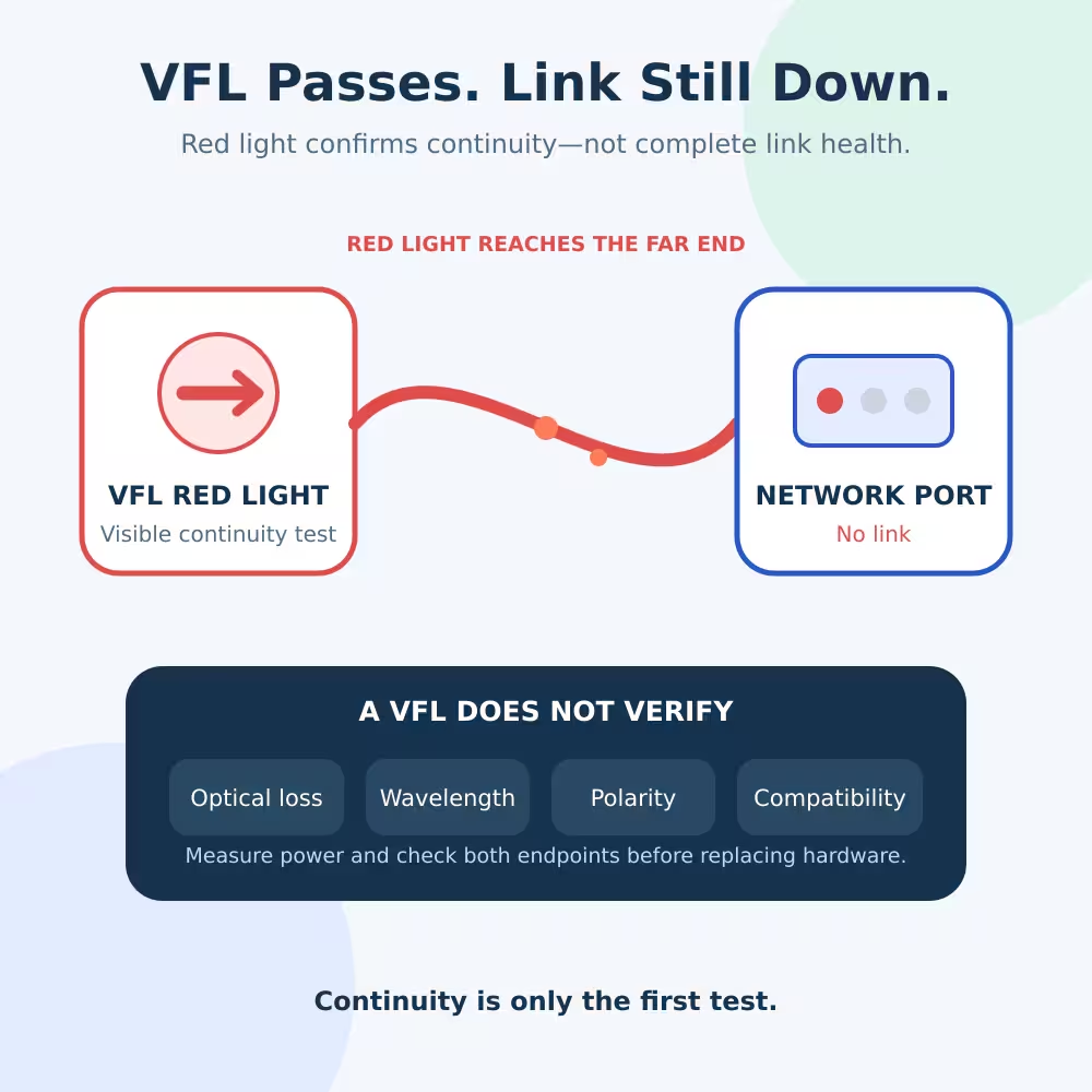
On a duplex link, Tx on one end must reach Rx on the other. If the link remains down, follow this Tx/Rx polarity check instead of repeatedly swapping unrelated settings. The referenced guide also separates rate, optical-standard, connector-cleanliness, and receive-power checks. luleey.com
For BiDi, do not swap strands—there is only one strand. Confirm the modules form a complementary wavelength pair.
5. Apply only documented port settings
Set the switch port to the optic’s supported speed or auto mode as required by the switch manual. Keep copper auto-negotiation separate from the optical line-rate question.
Randomly forcing duplex or speed can hide the real mismatch.
6. Verify the result at three levels
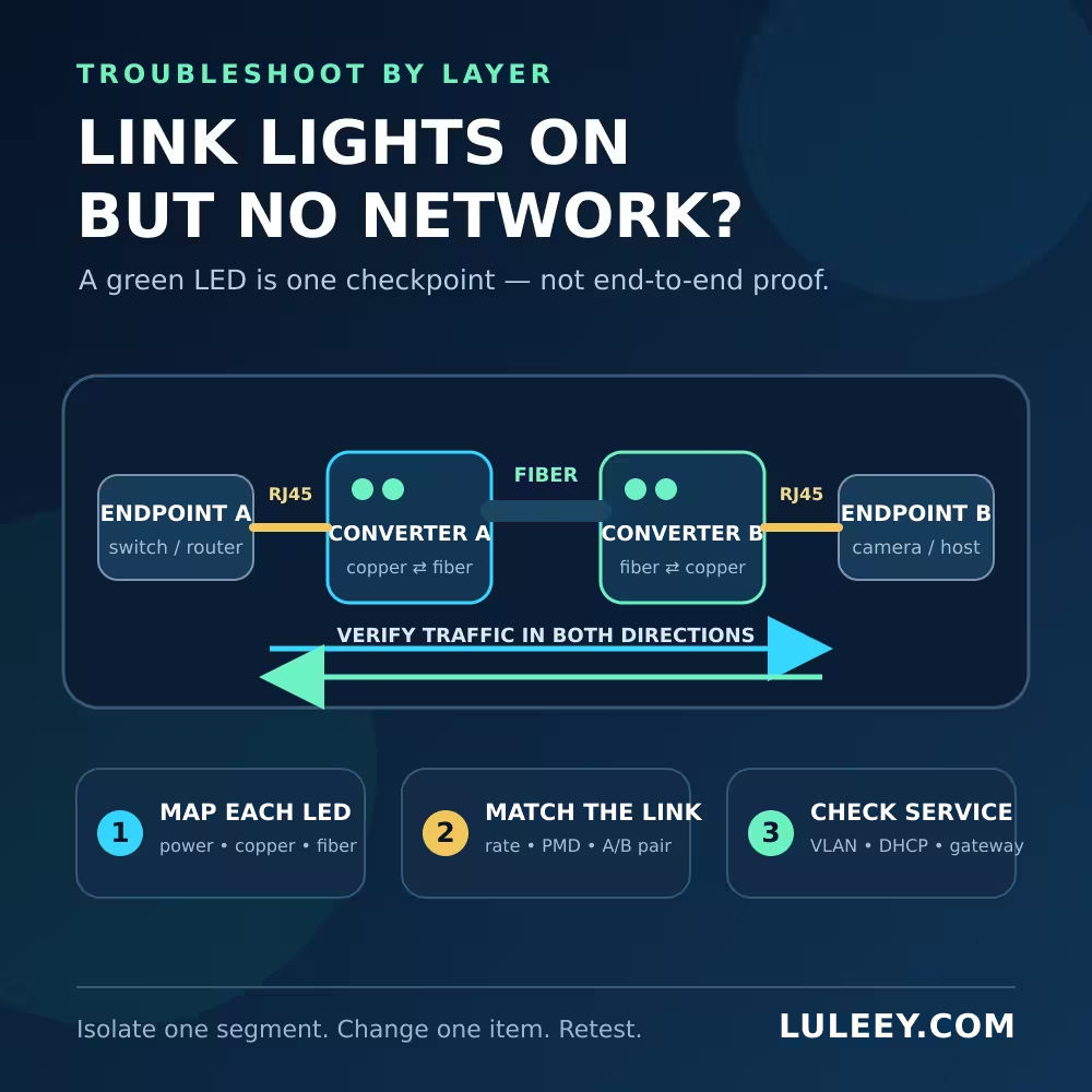
Check more than the link LED:
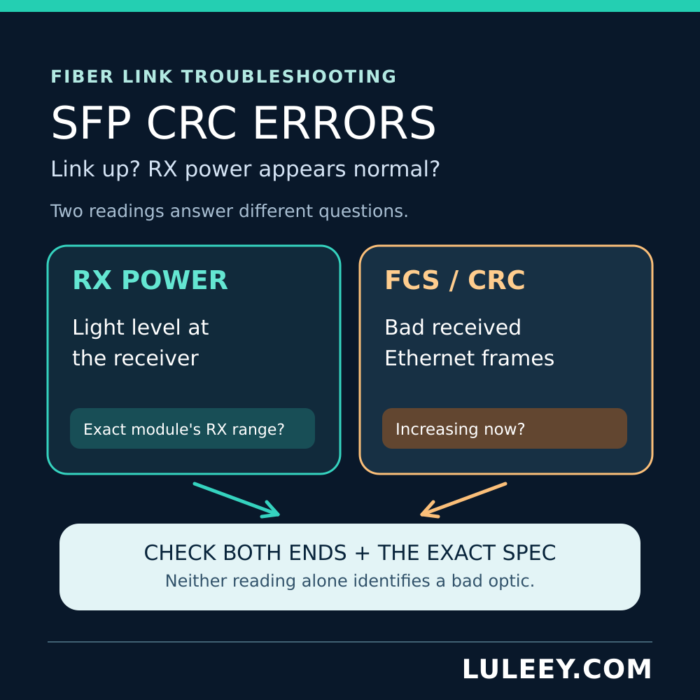
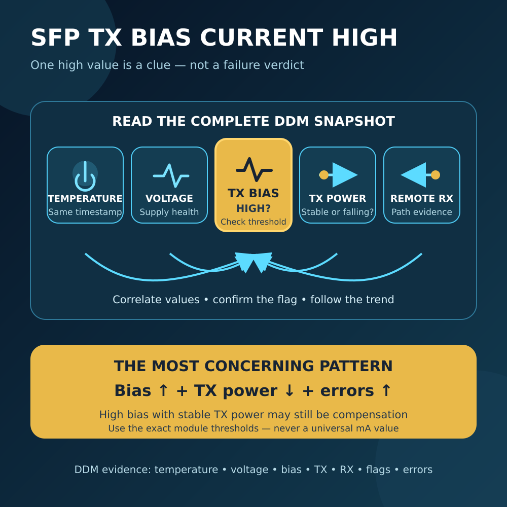
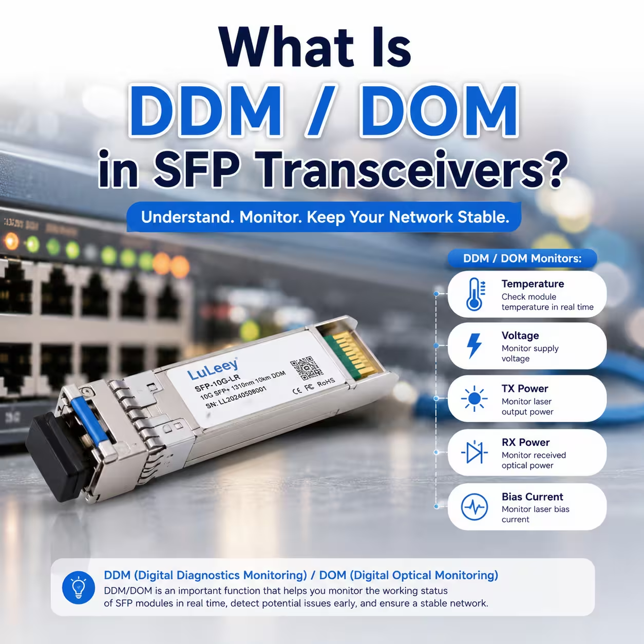
- Physical: Link is stable; received power is within the module’s specified window if digital diagnostics are available.
- Data link: Error, CRC, symbol, and flap counters do not climb during traffic.
- Service: The expected VLAN, IP, DHCP, PPPoE, or other service actually passes at the required rate.
If the LED is on but traffic still fails, the optical pairing may be correct while the problem sits in VLAN handling, MTU, addressing, or service configuration.
If the Link Still Does Not Come Up
Change one variable at a time. Start with a short, known-good fiber and a known-good matching module pair. Test each SFP in a documented compatible host. Then restore the original fiber path and compare receive power and error counters.
Use the worksheet above as the stopping rule: if one row cannot be verified, fix that mismatch before replacing everything.
Once you know the required Ethernet rate and optical specification, compare it with LuLeey’s verified copper-to-fiber media converter range and select only a model whose published host and optical interfaces match your design.
 SFP/SFP+ (1G/2.5G/5G/10G)
 SFP-T (1G/2.5G/10G)
 AOC Cable 10G/25G/40G/100G
 DAC Cable 10G/25G/40G/100G
 QSFP28 QSFP+ SFP28 100G/40G/25G
 Copper to Fiber Media Converters
 Fiber Media Converter PCBA Board
 OEO Fiber Media Converters
 Serial to Fiber Media Converters
 Video to Fiber Media Converters
 1000M GPON/EPON ONU
 10G EPON ONU/XG-PON/XGS-PON
 2.5G GPON/XPON STICK SFP ONU
 POE GPON/EPON ONU
 Wireless GPON/EPON ONT
 EPON OLT
 GPON OLT
 SFP PON Module
 Industrial Switches
 Managed Switches
 POE Switches
 Unmanaged Switches
 MTP/MPO Fiber Cables
 Fiber Optic Cassettes
 Fiber Optic Loopback
 Optic Cables and Fiber Pigtails
 Optical Splitters and Splitter Box
 Fiber Flange Connectors
 Optical Adapters
 Optical Attenuator
 Quick Connector and Connector Panel
 CATV Amplifier
 CATV Optical Receiver
 Visual Fault Locator
 OTDR
OTDR Optical Power Meter
 Fiber Optic Identifier
 Fiber Optic Cleaners
 Fiber Cleavers & Fiber Strippers
 Copper Tools


