Customs duties are the responsibility of customers, but standard logistics support DDP to most countries, duty-free such as US, DE, UK, CA, FR, IT, PL, AT, JP…





















































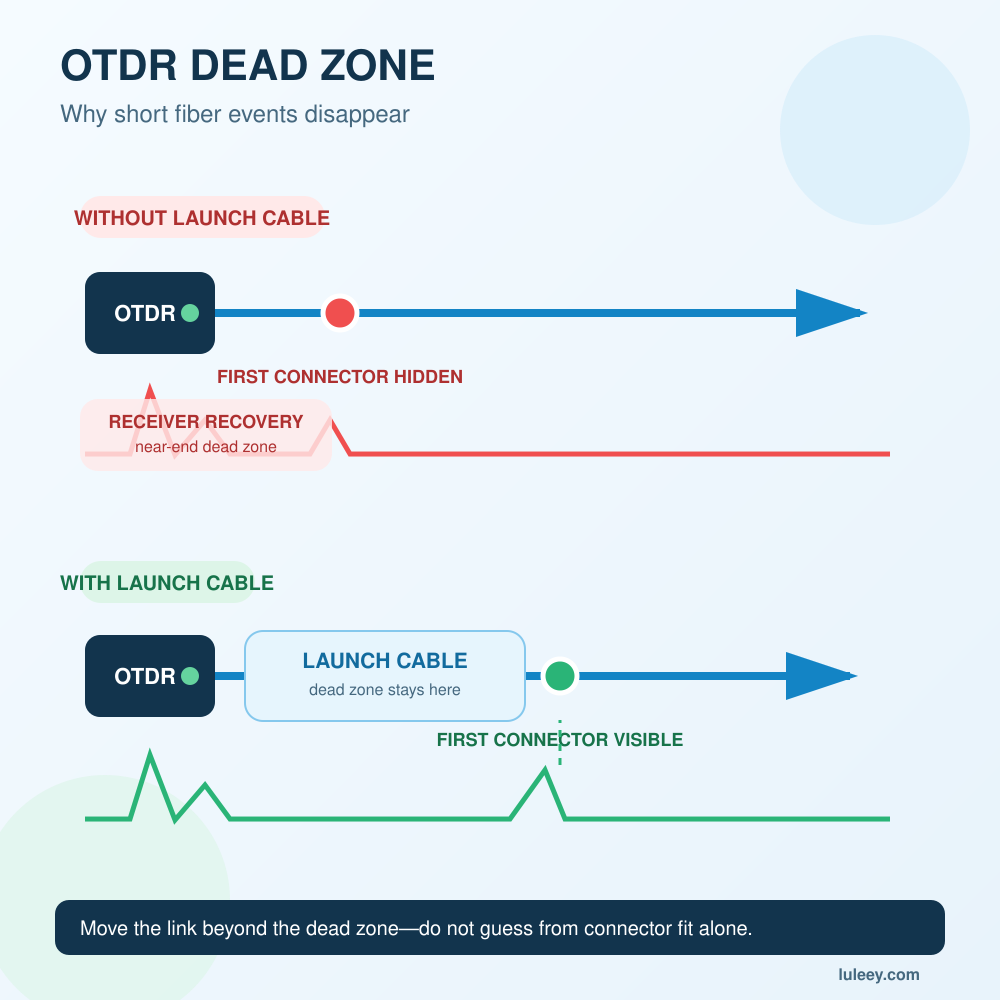
An OTDR dead zone is a section of the trace in which the instrument cannot reliably distinguish or measure an event. It often appears after a strong reflection, especially at the OTDR’s own output connector.
That is why a short fiber can be physically connected but still seem to “disappear” on the trace. The large initial reflection overloads the OTDR receiver, and the instrument needs time—and therefore fiber distance—to recover.
The usual fix is not to add an arbitrary length of cable. Use a launch cable long enough for the selected OTDR, pulse width and test range. Add a Receive Cable when the far-end connector must also be measured. For very short links, an optical loss test set may provide a more useful end-to-end loss result.
OTDR Dead Zone: The Quick Answer
| What you see | Likely reason | Practical next step |
|---|---|---|
| One large peak at the beginning | OTDR port reflection and receiver recovery | Inspect and clean the port, then use a suitable launch cable |
| First connector is hidden | The cable under test begins inside the near-end dead zone | Make the launch cable longer than the dead zone under the actual settings |
| Two nearby connectors appear as one event | Events are closer than the available spatial resolution | Use a shorter pulse if the signal-to-noise ratio permits |
| Far-end connector is shown only as the end of fiber | No backscatter exists after the last connector | Add a receive cable beyond the far end |
| Short link gives unstable dB/km results | Too little undistorted fiber is available for a reliable slope | Use an insertion-loss test for end-to-end loss |
| Dead zone grows after changing settings | A wider pulse or stronger reflection increases recovery distance | Recheck pulse width, connector condition and launch-cable length |
Do not compare two OTDR dead-zone specifications unless the test conditions and definitions are equivalent. Wavelength, pulse width, reflectance, averaging and the manufacturer’s measurement method can change the result.
How an OTDR Creates a Fiber Trace
An optical time-domain reflectometer sends short optical pulses into a fiber. It measures Rayleigh backscatter from the fiber and reflections from events such as connectors, mechanical splices and open ends.
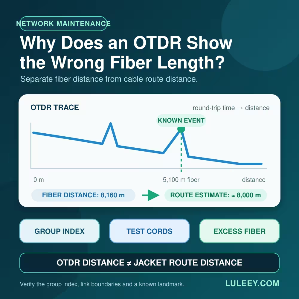
Because the light travels out and returns to the instrument, the OTDR uses the return time and the configured group index or index of refraction to estimate distance. It then displays the returned signal as a trace.
A connector normally creates a reflective peak. A fusion splice or bend may appear mainly as a change in the backscatter level. The slope between events represents fiber attenuation, although an OTDR infers loss from backscatter rather than measuring end-to-end transmitted power directly.
The Fiber Optic Association’s OTDR guide explains that the high-power test pulse and reflection at the instrument interface can overload the receiver. The recovery period creates the near-end dead zone.
Event Dead Zone vs Attenuation Dead Zone
OTDR datasheets commonly separate two related limits.
Event dead zone
The event dead zone describes how close two reflective events can be while still appearing as two separate events. ITU-T G.976 defines dead zone, in its OTDR/COTDR context, as the minimum distance at which two consecutive reflective events can be distinguished.
If two connectors are closer than this limit, their reflection peaks may merge. The trace may show one event even though two physical connections exist.
Attenuation dead zone
The attenuation dead zone is the longer recovery distance required before the backscatter trace becomes stable enough to measure the loss of a following event accurately.
An OTDR may therefore detect that an event exists before it can calculate that event’s loss reliably. An “event dead zone” specification does not prove that an accurate insertion-loss result is possible at the same distance.
The exact thresholds used for these specifications can vary. Use the definitions and test conditions in the exact OTDR manual rather than transferring one model’s numbers to another model.
Why a Launch Cable Reveals the First Connector
Without a launch cable, the cable under test begins immediately after the OTDR port. Its first connection can fall inside the initial recovery region.
A launch cable places a known length of fiber before the cable under test:
OTDR → launch cable → first connection → cable under test
The initial dead zone then falls within the launch cable. After the trace settles, the OTDR has a backscatter baseline before the first connection. That baseline lets the instrument locate the connection and estimate its loss and reflectance.
A launch cable has two jobs:
- Move the first test connection beyond the near-end dead zone.
- Provide fiber backscatter before that connection so the event can be evaluated.
It does not remove dead zones from the instrument. It moves the cable under test to a measurable part of the trace.
Why a Receive Cable Is Needed at the Far End
The final connector presents the opposite problem. If the fiber ends immediately after that connector, there is no normal backscatter baseline on the far side of the event.
Add a receive cable, also called a tail cord, after the cable under test:
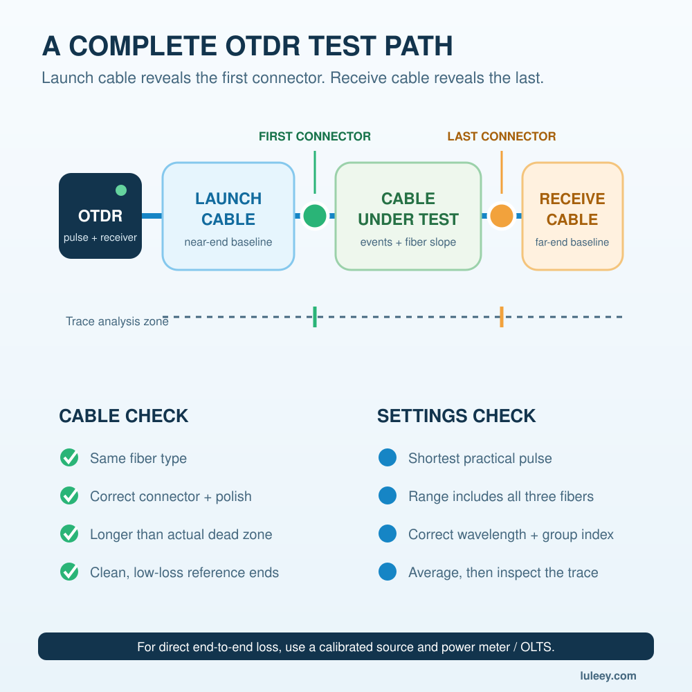
OTDR → launch cable → cable under test → receive cable
The receive cable provides backscatter after the final connection. This allows the OTDR to separate the far-end connector from the end of fiber and assess that connection.
Use both cables when the report needs the first and last connector. A launch cable alone may be sufficient for some fault-location or splice-monitoring jobs, but it cannot create fiber after the far-end connector.
How Long Should an OTDR Launch Cable Be?
There is no universal 100m, 500m or 1km answer.
The launch cable must extend beyond the dead zone produced by the actual test conditions. Required length depends on:
- OTDR model and receiver recovery
- Pulse width
- Test range
- Wavelength
- Reflectance at the OTDR and cable connectors
- Fiber type
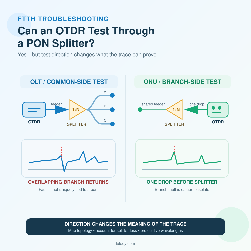
- Whether a splitter or high-loss path is present
- Event-resolution and dynamic-range requirements
A short pulse improves the ability to separate nearby events but sends less energy into the fiber. A longer pulse improves signal-to-noise ratio and distance reach, but reduces spatial resolution and normally creates a longer dead zone.
FOA gives 50–100m as a possible range for some short-distance, high-resolution tests and recommends at least 1km for single-mode long-distance testing. These are starting examples, not universal specifications.
LuLeey’s OTDR launch cable box page lists selectable connectors and lengths from 150m to 2km. Before ordering, confirm the required fiber mode, connector type and polish, length, and OTDR port interface.
How to Select Launch and Receive Cables
1. Match the fiber type
The launch and receive cables should match the fiber under test. Do not use a multimode launch fiber for a single-mode route, or mix 50/125µm and 62.5/125µm multimode fibers.
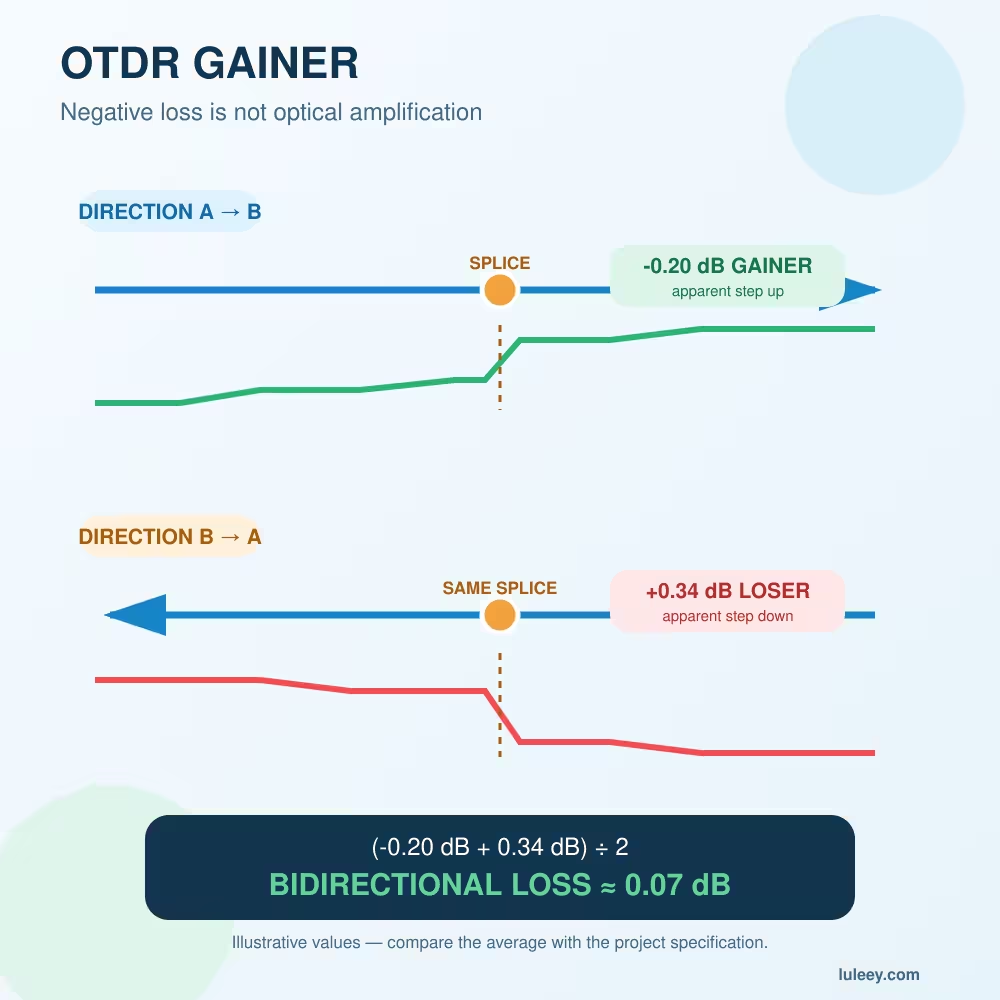
Bidirectional testing can help reveal apparent gainers caused by different backscatter coefficients.
2. Match the connector and polish
The cable must mate correctly with both the OTDR and the cable plant. SC, LC, FC and ST are physical connector families; UPC and APC describe different end-face geometries.
Do not directly mate APC and UPC connectors. A hybrid launch cable can use one connector at the OTDR end and another at the network end when both ends are correctly specified.
3. Choose enough length for the final settings
The launch cable must be longer than the initial dead zone, and the receive cable must provide enough visible backscatter after the far-end event. Recheck this after increasing pulse width or range.
4. Use low-loss, clean reference connectors
A dirty or damaged launch connector can create a large reflection, extend the recovery tail and make a good cable appear faulty.
The FOA reference-cable guide emphasizes matching fiber and connectors, sufficient length and clean, low-loss reference connections.
Seven Steps for Testing a Short Fiber with an OTDR
Step 1: Confirm the fiber is safe to test
Do not connect a general-purpose OTDR to an unknown live link. Confirm that the fiber is inactive, or use an instrument and filtered test method specifically designed for the live PON wavelengths and operating conditions.
Step 2: Inspect and clean
Inspect the OTDR port, launch cable and accessible network connectors with suitable equipment. Never use a direct-view microscope until optical safety has been confirmed.
Step 3: Connect the complete test path
Use:
OTDR → launch cable → cable under test → receive cable
Record the launch- and receive-cable lengths so you do not mistake their events for the network under test.
Step 4: Start with the shortest practical pulse
A short pulse gives better event separation. If the trace is too noisy, increase averaging before making a large pulse-width change.
Step 5: Set an appropriate range and group index
The range must include the launch cable, cable under test and receive cable. An incorrect group-index setting shifts the reported distances.
Step 6: Identify the network boundaries
Locate the end of the launch cable and start of the receive cable. Analyze the cable under test between those two points.
Step 7: Test from both directions when event loss matters
Differences in backscatter between joined fibers can produce an apparent gainer in one direction and excessive loss in the other. Bidirectional traces provide a more reliable splice-loss assessment.
Common OTDR Dead-Zone Mistakes
Using a normal patch cord as the launch cable
A one- or two-metre jumper may protect the OTDR port, but it is not automatically long enough to move the first event beyond the dead zone.
Selecting a long pulse because the trace looks cleaner
The trace may become less noisy, but nearby events can merge and the dead zone can grow. Clean appearance is not the same as better resolution.
Testing with only a launch cable and approving the last connector
Without receive fiber after the last connector, the OTDR cannot evaluate the far-end connection in the same way as an intermediate event.
Treating every peak as part of the installed link
The OTDR port, launch cable connectors, adapters and receive cable all appear on the trace. Label their expected distances first.
Trusting automatic event tables without viewing the trace
Merged events, ghosts, noise and recovery tails can be misclassified. Always examine the trace and physical route.
Replacing an insertion-loss test with OTDR results
An OTDR is useful for locating events. For direct end-to-end cable-plant loss, use a calibrated light source and power meter with the required reference method.
When an OTDR Is the Wrong Tool
Choose the tool according to the question:
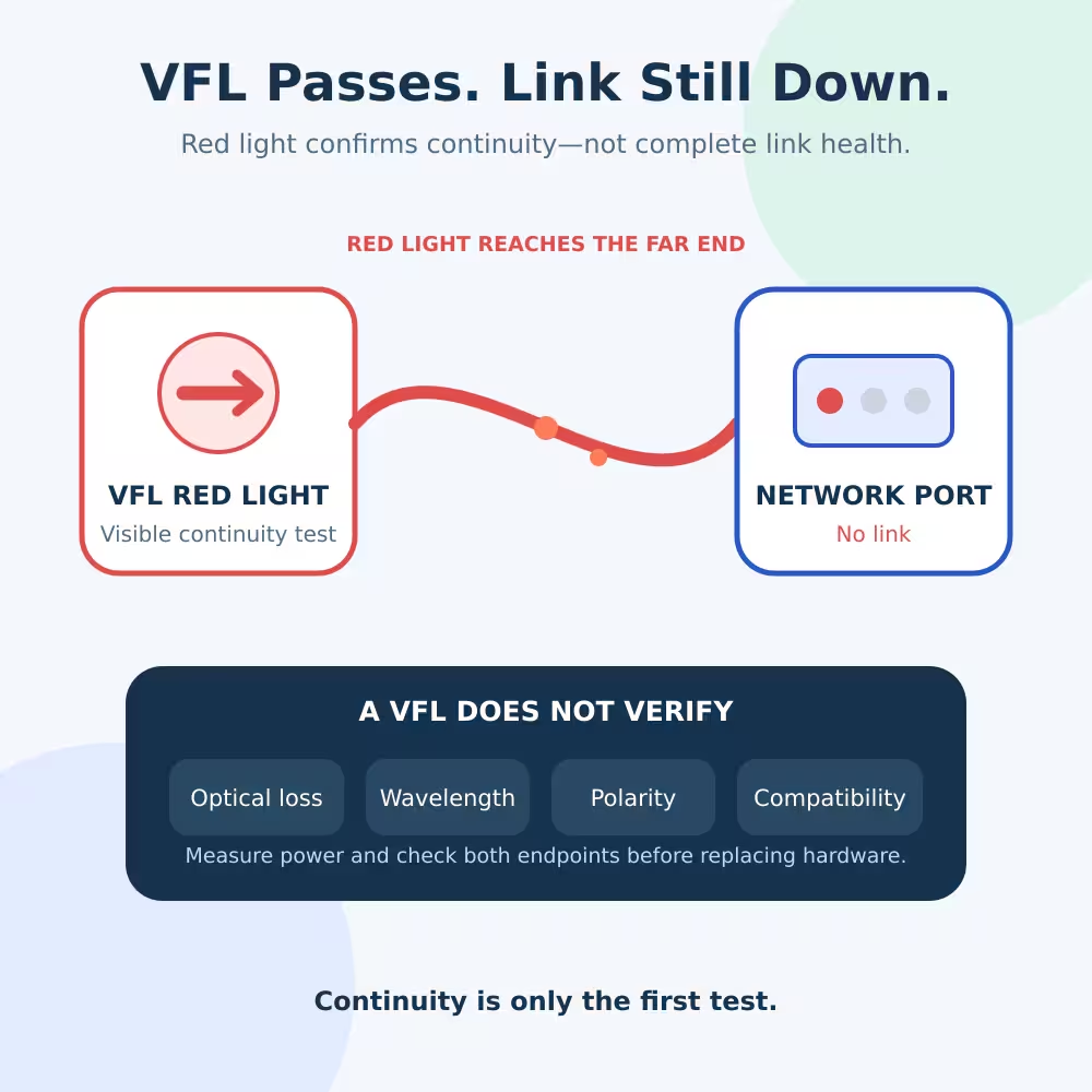
- Continuity or fiber identification: Visual fault locator
- Actual power at one point: Optical power meter
- End-to-end insertion loss: Light source and power meter or OLTS
- Location of a break, bend, connector or splice: OTDR
- Live PON wavelength-selective power: Compatible PON power meter and method
LuLeey’s guide on why a fiber can pass a VFL test but still have no link explains why visible continuity does not prove acceptable loss, wavelength, polarity or system compatibility.
Final Answer
An OTDR dead zone can hide a real event when the instrument has not recovered from a strong reflection or when two events are closer than its available resolution.
For a short fiber test:
- Use a launch cable long enough for the final pulse width and range.
- Add a receive cable when the far-end connector must be measured.
- Match fiber type, connector and polish.
- Start with a short pulse and appropriate range.
- Inspect and clean every reference connection.
- Use bidirectional testing when splice-loss accuracy matters.
- Use an OLTS when the goal is direct end-to-end insertion loss.
Before selecting equipment from LuLeey’s OTDR and launch-cable range, provide the fiber type, connectors, route length, shortest event spacing, required wavelength, live or dark-fiber status, and OTDR model.


 SFP/SFP+ (1G/2.5G/5G/10G)
 SFP-T (1G/2.5G/10G)
 AOC Cable 10G/25G/40G/100G
 DAC Cable 10G/25G/40G/100G
 QSFP28 QSFP+ SFP28 100G/40G/25G
 Copper to Fiber Media Converters
 Fiber Media Converter PCBA Board
 OEO Fiber Media Converters
 Serial to Fiber Media Converters
 Video to Fiber Media Converters
 1000M GPON/EPON ONU
 10G EPON ONU/XG-PON/XGS-PON
 2.5G GPON/XPON STICK SFP ONU
 POE GPON/EPON ONU
 Wireless GPON/EPON ONT
 EPON OLT
 GPON OLT
 SFP PON Module
 Industrial Switches
 Managed Switches
 POE Switches
 Unmanaged Switches
 MTP/MPO Fiber Cables
 Fiber Optic Cassettes
 Fiber Optic Loopback
 Optic Cables and Fiber Pigtails
 Optical Splitters and Splitter Box
 Fiber Flange Connectors
 Optical Adapters
 Optical Attenuator
 Quick Connector and Connector Panel
 CATV Amplifier
 CATV Optical Receiver
 Visual Fault Locator
 OTDR
OTDR Optical Power Meter
 Fiber Optic Identifier
 Fiber Optic Cleaners
 Fiber Cleavers & Fiber Strippers
 Copper Tools


