Customs duties are the responsibility of customers, but standard logistics support DDP to most countries, duty-free such as US, DE, UK, CA, FR, IT, PL, AT, JP…





















































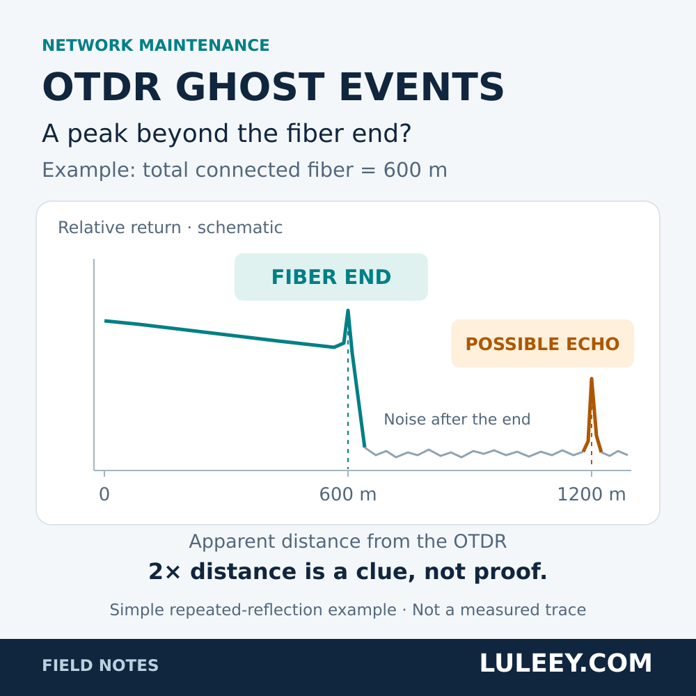
OTDR ghost events are reflection peaks that appear at positions where no physical event exists. They can make a short fiber look longer or suggest a connector that is not on the route.
A ghost is a measurement artifact. The reflection that produces it, however, may come from a real connection that needs attention. Before replacing cable or reopening a splice enclosure, check the trace against the actual test path.
How to Recognize OTDR Ghost Events
Look for several clues together:
| Trace observation | Why it is suspicious |
|---|---|
| A peak appears beyond the independently verified end of all connected fiber | There should be no physical connector at that displayed distance |
| Peaks repeat at regular intervals after a strong reflection | Light may be making additional trips between reflective interfaces |
| A peak has no corresponding downward step in the fiber backscatter | It may be an echo rather than a lossy connection |
The FOA OTDR guide describes these repeated-reflection artifacts. None of the clues is sufficient on its own. A real connection can have loss too small to resolve, and a noisy trace may not provide a usable baseline. Beyond the fiber end, do not report “0 dB loss” simply because the instrument has no fiber backscatter to compare.
Why a 600 m Test Path Can Show a Peak Near 1200 m
An OTDR converts the return time of light into distance. If reflected light travels back and forth again before reaching the receiver, the extra delay can be displayed as extra distance.
For a simple example, suppose all connected fiber totals 600 m, including any test cords. Repeated reflection between the near end and the reflective far end can produce an echo near 1200 m on the trace. That does not mean another 600 m of cable exists.
This is an illustrative case, not a rule that every ghost occurs at twice the installed cable length. Other reflecting interfaces and test-path lengths can produce different patterns.

A Practical Retest Sequence
Use the following procedure on disconnected, dark fiber. Confirm the fiber is safe before inspection; never look into an optical port or fiber end.
1. Save the original trace and check the distance reference
Record the suspected event distance, wavelength, pulse width, range and group-index setting. Keep the trace, not just its automatic event table.
Add the launch cable, installed link and receive cable lengths. Check whether the instrument displays distance from its port or has applied launch-cable compensation. A peak beyond the installed link might simply be the end of the receive cable.
2. Check the strong reflection before the suspect peak
Inspect the accessible mating surfaces with suitable inspection equipment, clean as needed and inspect again. Reseat correctly matched connectors or substitute a known-good test cord when appropriate. Keep the acquisition settings unchanged for this comparison.
The aim is to reduce an unintended reflection at its source. Do not force an APC connector against a UPC interface or sharply bend fiber to make the peak disappear.
3. Check the range and pulse width
The acquisition range must cover the complete connected test path. If it is too short, correct it and acquire a new trace.
If two nearby events are difficult to separate, try a shorter pulse while keeping the far end visible above the noise. Change one setting at a time and record it.
A shorter pulse can improve event resolution, but it also reduces the signal available for longer-distance measurements. Compare the event’s position, the trace around it and the known route; a change in peak height alone does not establish whether it is a ghost.
4. Compare the result with the physical route
If the suspect peak diminishes when the earlier reflection is corrected, while the known route events remain consistent, the ghost explanation becomes stronger.
If uncertainty remains, test from the opposite end and map both traces to the same physical locations, accounting for test cords. A repeatable event at a real route position needs investigation. If the available resolution cannot separate it, leave it unresolved rather than deleting it from the report.
Check the Test Setup Before Buying More Equipment
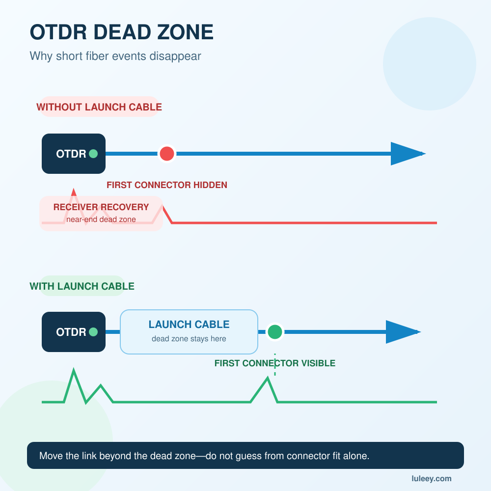
Launch and receive cables provide fiber before the first connection and after the last connection so those boundaries can be evaluated. They do not guarantee that every ghost will disappear.
Use LuLeey’s OTDR dead-zone guide to check whether the selected pulse and reference cables can resolve the connections you need to inspect.
For a single-mode setup needing a reference cable, LuLeey’s single-mode OTDR launch cable box lists several connector combinations and length options. Match each connector and polish to its mating interface, then select length for the actual test settings; a longer box alone is not a ghost-removal method.
What to Keep in the Test Report
Keep the original trace, the retest, the setting changes and the evidence supporting your interpretation. Do not hide a questionable peak by raising the event threshold.
Review the saved trace alongside the event table. Check your instrument’s manual for its event-detection thresholds, and record any changes used for the retest. A label is a starting point for investigation, not a substitute for matching the event to a physical location.
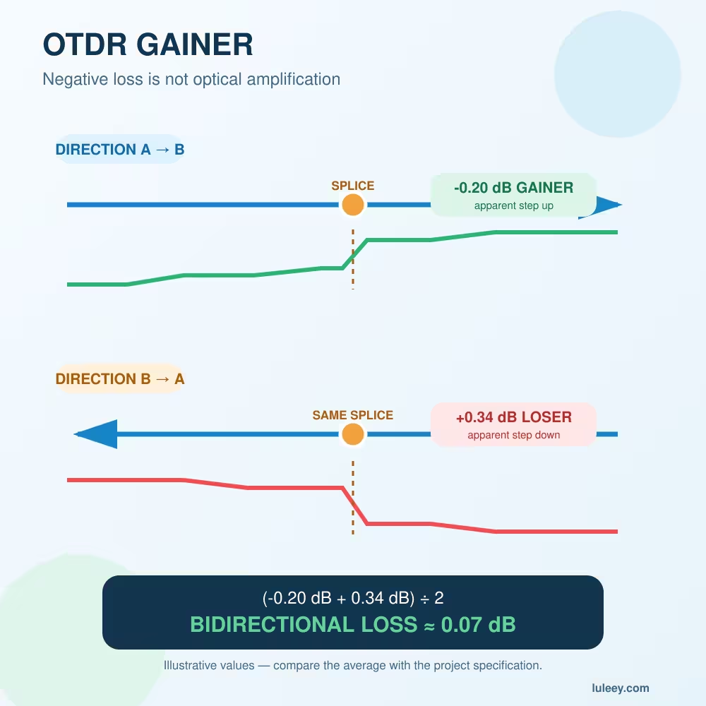
Your next step: mark the verified fiber end on the original trace, identify the strong reflection preceding the suspect peak, and make one controlled retest. If the trace instead shows negative splice loss, continue with LuLeey’s OTDR gainer guide, which addresses a different measurement effect.


 SFP/SFP+ (1G/2.5G/5G/10G)
 SFP-T (1G/2.5G/10G)
 AOC Cable 10G/25G/40G/100G
 DAC Cable 10G/25G/40G/100G
 QSFP28 QSFP+ SFP28 100G/40G/25G
 Copper to Fiber Media Converters
 Fiber Media Converter PCBA Board
 OEO Fiber Media Converters
 Serial to Fiber Media Converters
 Video to Fiber Media Converters
 1000M GPON/EPON ONU
 10G EPON ONU/XG-PON/XGS-PON
 2.5G GPON/XPON STICK SFP ONU
 POE GPON/EPON ONU
 Wireless GPON/EPON ONT
 EPON OLT
 GPON OLT
 SFP PON Module
 Industrial Switches
 Managed Switches
 POE Switches
 Unmanaged Switches
 MTP/MPO Fiber Cables
 Fiber Optic Cassettes
 Fiber Optic Loopback
 Optic Cables and Fiber Pigtails
 Optical Splitters and Splitter Box
 Fiber Flange Connectors
 Optical Adapters
 Optical Attenuator
 Quick Connector and Connector Panel
 CATV Amplifier
 CATV Optical Receiver
 Visual Fault Locator
 OTDR
OTDR Optical Power Meter
 Fiber Optic Identifier
 Fiber Optic Cleaners
 Fiber Cleavers & Fiber Strippers
 Copper Tools


