Customs duties are the responsibility of customers, but standard logistics support DDP to most countries, duty-free such as US, DE, UK, CA, FR, IT, PL, AT, JP…





















































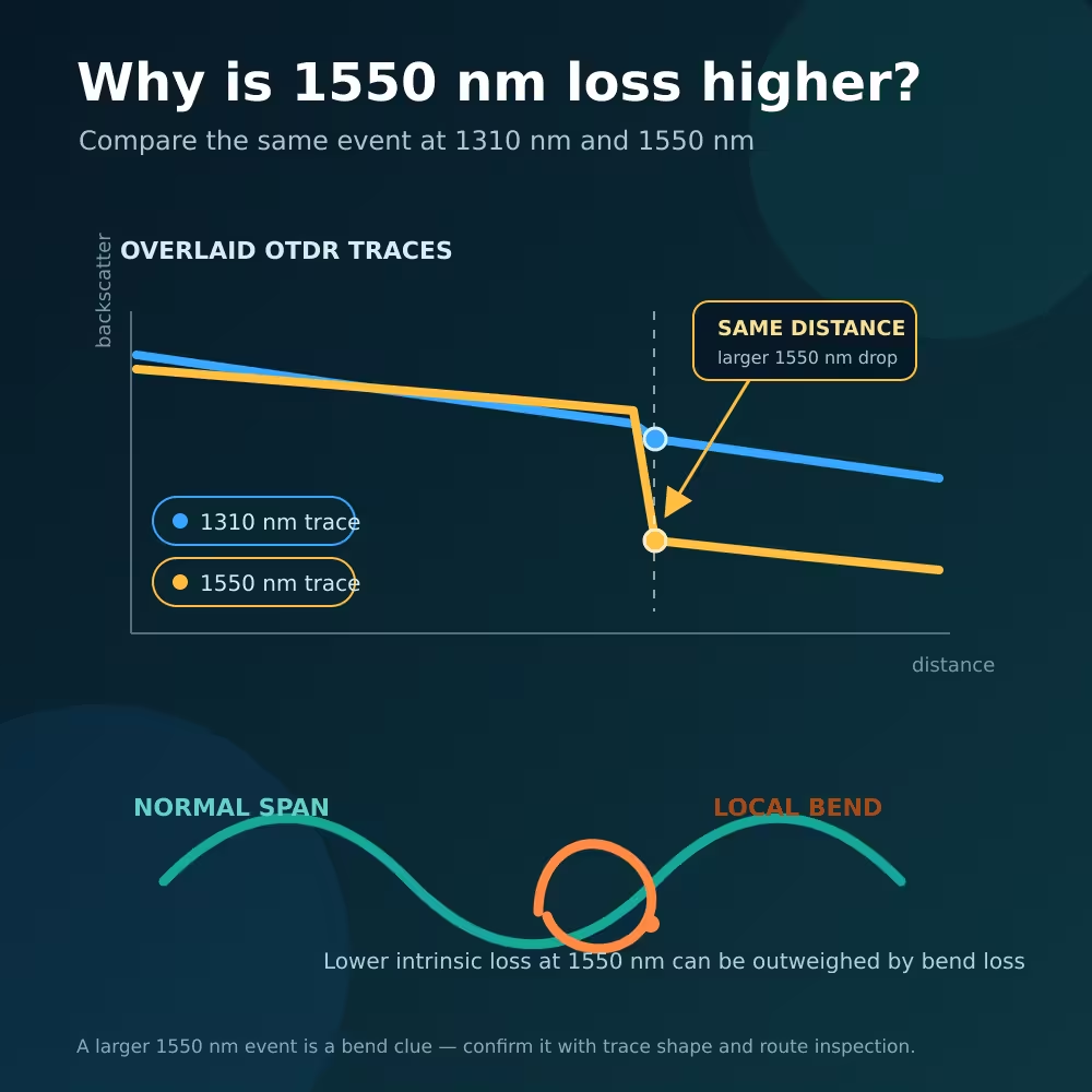
If you find Fiber Loss higher at 1550nm than 1310nm, a bend or cable stress is one of the first things to investigate. Longer wavelengths are generally more sensitive to Macrobending, so a tight loop, crushed cable, sharp corner or poorly routed splice tray can create much more excess loss at 1550nm.
That does not mean Single-Mode Fiber naturally has higher attenuation at 1550nm. On an undisturbed G.652D span, the opposite is commonly true: the fiber’s attenuation per kilometer is usually lower at 1550nm than at 1310nm. The surprising result occurs when a localized, wavelength-sensitive loss outweighs that normal difference.
Use the two OTDR traces as evidence, not as a verdict. Align the events by distance, inspect the trace shape, check the physical route and confirm the repair with the test method required by the project.
Fiber Loss Higher at 1550nm Than 1310nm: Quick Answer
| Observation | More likely explanation | First useful check |
|---|---|---|
| 1550nm has a larger non-reflective drop at the same distance | Macrobend or local cable stress | Inspect the tray, loop, tie, corner or enclosure at that distance |
| The whole 1550nm trace has a steeper slope | Distributed stress, wrong test setup, unusual fiber or instrument issue | Verify wavelength, settings, fiber type and a known-good reference |
| One splice changes greatly with test direction | Backscatter or mode-field mismatch may affect the OTDR result | Test from both ends and average the signed splice readings |
| A sharp reflective peak appears at both wavelengths | Connector, mechanical interface, open end or contamination is more likely | Inspect and clean the correct interface safely |
| End-to-end loss fails at 1550nm but no clear OTDR event appears | Several small bends, short events, dead zones or measurement differences | Compare overlaid traces and perform approved insertion-loss testing |
| 1310nm and 1550nm both become high at the same event | Real splice loss, severe bend or damaged interface | Check both directions, reflectance and the physical location |
There is no universal differential-loss number that proves a bend. OTDR uncertainty, pulse width, marker placement, fiber type and the project limit all matter.
Two Types of Loss Are Being Compared
The phrase “fiber loss” can describe two different things.
Intrinsic span attenuation
This is the gradual loss along a length of fiber, normally expressed in dB/km. For a typical low-water-peak G.652D fiber, attenuation around 1550nm is usually lower than at 1310nm.
For example, LuLeey’s verified G.652D bare fiber and OTDR test-fiber page lists:
- 1310nm attenuation: no more than 0.36dB/km
- 1550nm attenuation: no more than 0.22dB/km
Those are product-page maximum values for that listed fiber, not universal values for every installed cable. They illustrate why a clean span can show a shallower OTDR slope at 1550nm.
Localized excess loss
A tight bend changes how well the guided optical field remains confined to the core. Some light radiates out of the guided mode. This added macrobending loss increases with longer wavelength, and it can be concentrated in only a few centimeters of the route.
A single local bend can therefore add more loss at 1550nm than the fiber saves through its lower per-kilometer attenuation. The final end-to-end result may then be worse at 1550nm even though the undisturbed fiber itself is normally better at that wavelength.
Do not compare only the total loss numbers. Separate the gradual span slope from discrete events and inspect where the traces begin to diverge.
Why 1550nm Is More Sensitive to Bending
At a longer wavelength, the guided optical field extends farther from the core and is generally less tightly confined. When the fiber is curved too sharply, more of that field can escape.
The exact loss depends on:
- Fiber design and mode field diameter
- Bend radius
- Number of turns
- Length of fiber under stress
- Cable construction
- Wavelength
- Temperature and mechanical conditions
ITU-T G.657 states that macrobending loss varies with wavelength, radius and number of turns, and that optical bending loss increases with wavelength. It also warns that the finished cable construction and installation method influence field performance.
This is why 1550nm is useful for finding installation stress that may be weak or invisible at 1310nm. A 1625nm maintenance wavelength can be even more sensitive, but it must be supported by the instrument and approved for the actual network.
Higher sensitivity does not mean every 1550nm event is a bend. It means the wavelength difference is a diagnostic clue that should agree with the event shape and route.
What a Bend Looks Like on 1310nm and 1550nm OTDR Traces
A simple macrobend often appears as a non-reflective step at the same distance on both traces:
- The 1310nm step is small or difficult to see.
- The 1550nm step is larger.
- There may be no reflective spike.
- The backscatter after the event remains lower because power was lost at the bend.
The Fiber Optic Association’s OTDR FAQ demonstrates this classic comparison: a deliberately stressed single-mode cable produced a clear non-reflective loss at 1550nm and much less evidence at 1310nm. The example is instructional, not a universal loss threshold.
Suppose an event at the same mapped distance reports:
- 1310nm event loss: 0.08dB
- 1550nm event loss: 0.72dB
The wavelength difference is:
Differential event loss = 0.72dB − 0.08dB = 0.64dB
That pattern is consistent with a bend. The numbers are illustrative only. Before accepting the diagnosis, confirm that the traces used comparable settings, the event is not inside a dead zone and the physical route contains a plausible stress point.
ITU-T G.650.3 Amendment 1 formalizes a two-wavelength macrobending indicator for installed single-mode links. It explains that, with 1310nm as the shorter wavelength, macrobend detection sensitivity improves as the second wavelength becomes longer.
Bend, Splice or Connector?
A bend is usually non-reflective and wavelength-sensitive
A tight loop or pinch commonly makes a step without a reflection peak, and the loss becomes stronger at 1550nm. Likely locations include:
- A splice tray with fiber routed outside its retainers
- A closure lid pressing on a buffer tube
- A cable tie pulled too tightly
- A drop cable folded behind an outlet
- A patch cord trapped under equipment
- A sharp wall, cabinet or door-frame corner
- A reel or storage loop below the cable’s allowed radius
The OTDR distance points to where to inspect, but its distance accuracy depends on the configured group index and the difference between optical route length and map distance.
A fusion splice can be confused with a bend
A fusion splice is also normally non-reflective. If a splice exists at the same distance, the event could be a poor splice, a bend next to the protector sleeve or both.
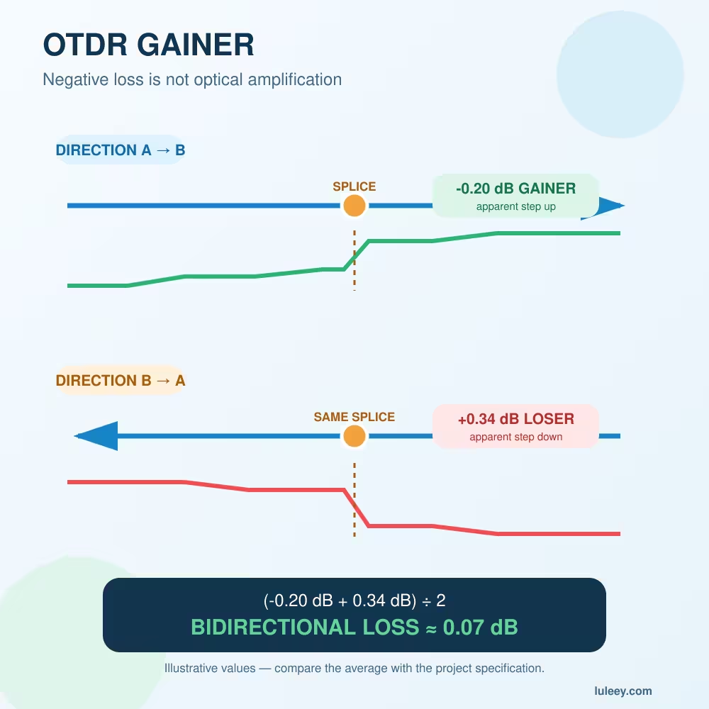
Splices between fibers with different backscatter coefficients can show a gainer in one direction and a higher-loss event in the other. That directional effect is not the same as a wavelength-sensitive bend.
Test from both ends when splice acceptance matters. Keep the signs and calculate:
Bidirectional splice loss = (A→B signed loss + B→A signed loss) ÷ 2
LuLeey’s guide to OTDR gainers and negative splice loss explains how to pair the same physical event and average it correctly.
A connector usually adds reflection evidence
An open connector, air gap, mechanical interface or badly contaminated end face often produces a reflective peak. Inspect and clean accessible connectors using the network owner’s approved procedure, then retest.
Do not assume every reflective event is dirt or every non-reflective event is a bend. APC interfaces, low-reflectance connectors, automatic event algorithms and nearby dead zones can change what the trace looks like.
Make the 1310nm and 1550nm Comparison Fair
The comparison is only useful when the two measurements describe the same physical link under controlled conditions.
Use the same:
- Test direction
- Launch and receive fibers
- Connector interfaces and cleaning condition
- Distance range
- Group-index setting appropriate to the wavelength and fiber
- Event-analysis method
- Route state and environmental condition
Use equivalent pulse width and averaging quality where practical. The settings do not always have to be numerically identical if the instrument applies wavelength-specific optimization, but they must provide comparable spatial resolution and noise performance around the event.
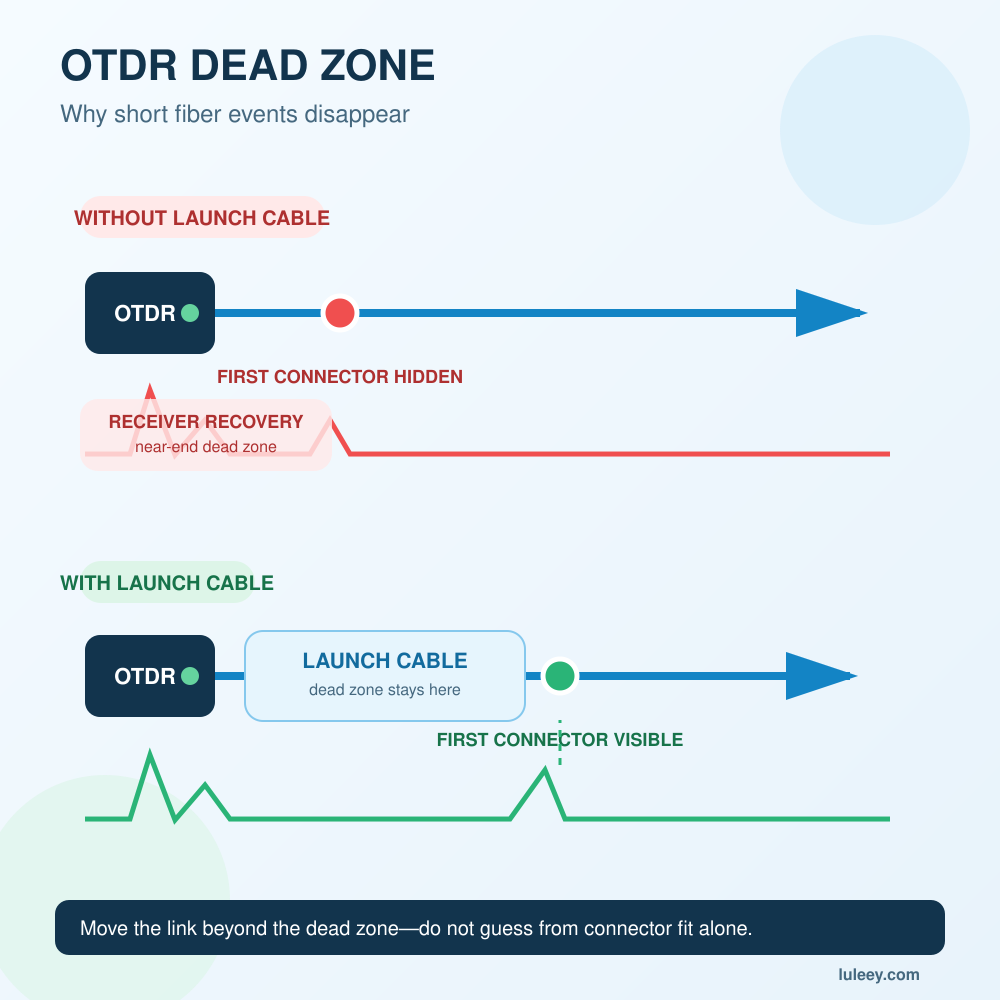
A longer pulse may reach farther, but it also increases dead zones and can merge nearby events. Start with the shortest pulse that reaches the area of interest, then increase averaging before making a large pulse-width change.
Use a launch cable to create a stable backscatter section before the first connection, and a receive cable when the far-end connector must be evaluated. LuLeey’s single-mode OTDR launch cable box page lists 9/125µm single-mode options, 150m–2km lengths and SC, FC, LC or ST connector choices with UPC or APC variants.
Match the launch and receive fibers, connector family and polish to the test link. A launch cable that introduces its own bend can create a false event before the cable under test.
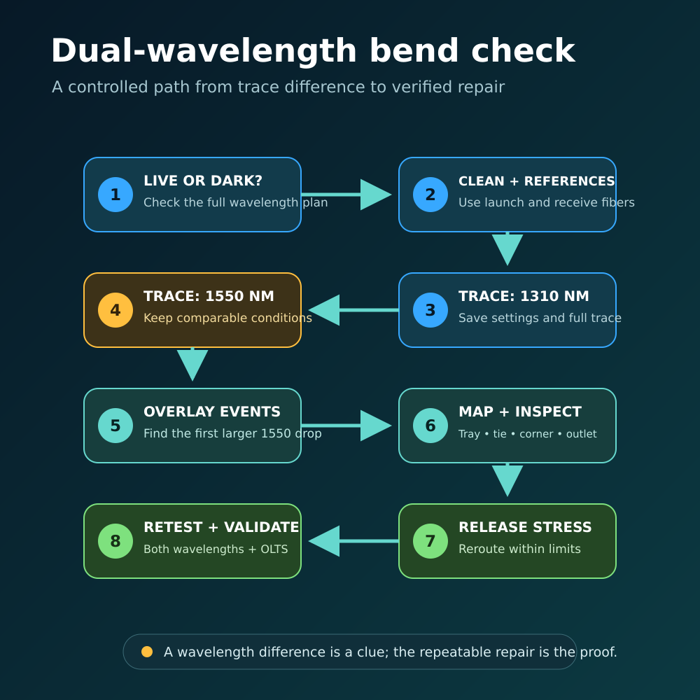
An Eight-Step Troubleshooting Workflow
Step 1: Confirm whether the fiber is live
Ask the network owner and check the wavelength plan. Do not infer a dark fiber from an unplugged-looking connector or an ONU LED.
Step 2: Record the working context
Save the route, fiber type, cable construction, expected events, connector polish, current service state and earlier baseline traces. Note whether the problem appeared after installation, enclosure work, temperature change or cable movement.
Step 3: Inspect and clean accessible interfaces
Use approved inspection and cleaning tools. Never look into a fiber. Treat every unknown connector as active until the correct procedure proves otherwise.
Step 4: Set up launch and receive fibers
Choose lengths suitable for the OTDR pulse, dead zones and link. Confirm that the test cords themselves are clean, correctly polished and not tightly coiled.
Step 5: Acquire the 1310nm trace
Set the correct range and group index. Begin with a short practical pulse, add averaging and save the full trace plus event table.
Step 6: Acquire the 1550nm trace
Keep the test direction and route unchanged. Use comparable resolution and noise quality. Save the settings rather than recording only the automatic loss values.
Step 7: Overlay and map the events
Align the traces by distance. Look for the first point where 1550nm drops more than 1310nm. Match that distance to splice trays, closures, slack loops, corners, cable ties, patch panels and customer outlets.
If a splice is involved, test from the other end and average the signed readings. If the event is reflective, inspect the corresponding connector or mechanical interface.
Step 8: Correct and validate
Release the cable stress or reroute the fiber according to the finished cable’s installation instructions. Repeat both wavelength tests with the same method.
When the project requires end-to-end certification, also use the approved light source and power meter or OLTS method. An OTDR locates and characterizes events from returned light; it is not a direct substitute for every insertion-loss acceptance method.
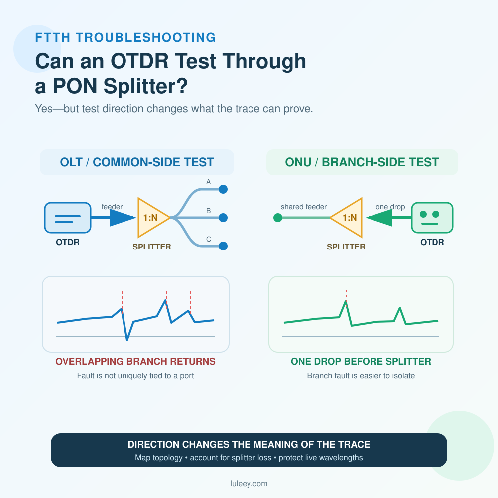
Can You Run This Test on a Live PON?
Only with equipment and procedures approved for the exact live system.
A normal 1310nm or 1550nm OTDR can overlap service or overlay wavelengths, interfere with traffic or receive incoming light from active equipment. For example, 1550nm may be used for an RF-video overlay or another optical service. XG-PON, XGS-PON and coexistence systems introduce additional wavelengths that must also be considered.
For in-service testing, verify:
- The complete operational wavelength plan
- OTDR test wavelength and output power
- Built-in filter passband and isolation
- Maximum incoming-power tolerance
- Approved connection point
- OLT, ONU, coexistence element and overlay requirements
- Network-owner authorization and maintenance procedure
The fact that 1625nm is more bend-sensitive does not make an unfiltered 1625nm OTDR safe on every live PON. Confirm the exact instrument variant and network architecture first.
Does G.657A2 Fiber Prevent This Problem?
G.657A2 fiber provides better macrobending performance than conventional G.652D, but it does not eliminate bend loss or mechanical damage.
ITU-T G.657 defines category A fibers as compliant with G.652.D and identifies G.657.A2 as suitable for a smaller design radius than A1. The standard also makes clear that field performance depends on cable construction and installation practice.
That distinction matters. A bare-fiber category does not give permission to fold, crush, staple or tightly tie a finished cable. The cable jacket, strength members, connector boot, adhesive method and long-term strain all affect the installed result.
LuLeey’s G.657A2 FTTR transparent fiber cable page lists a 0.9mm indoor transparent construction with SC/APC, SC/UPC, FC/APC, LC/UPC and headless options. The page describes it as bend-resistant for indoor FTTR/FTTH routing, but it does not publish a complete installed bend-radius rule. Confirm the ordered cable’s routing and fixing instructions for the real site.
Choosing a LuLeey Test Setup
LuLeey’s MINI OTDR LL-OTDR-1000 page lists several available OTDR laser-tube wavelengths, including 1310nm and 1550nm, plus pulse widths from 10ns to 6µs. However, the current option wording does not clearly establish which wavelengths are combined in each ordered hardware variant.
Before selecting an OTDR for dual-wavelength bend troubleshooting, provide LuLeey with:
- Exact fiber and cable type
- Link length and expected event spacing
- Required 1310nm and 1550nm capability in the same test plan
- Live or dark test condition
- PON generation and full wavelength plan, if applicable
- Required filtering and incoming-power tolerance
- Connector family and APC/UPC polish
- Launch and receive fiber lengths
- Required event resolution, dynamic range and report format
- Project acceptance method and limits
Ask LuLeey to confirm the exact ordered OTDR variant, wavelength combination, connector option and live-network suitability. A wavelength appearing somewhere in a product specification is not proof that every order option includes it.
Final Answer
Fiber loss can be higher at 1550nm than at 1310nm when a localized bend or installation stress adds wavelength-sensitive loss. This does not contradict the normal lower attenuation coefficient of undisturbed single-mode fiber at 1550nm.
Use this order:
- Confirm whether the fiber is live and identify the wavelength plan.
- Inspect and clean the test interfaces.
- Use suitable launch and receive fibers.
- Acquire comparable 1310nm and 1550nm traces from the same direction.
- Overlay the traces and locate the first wavelength-dependent event.
- Distinguish a non-reflective bend clue from connector reflection and directional splice error.
- Inspect the physical route at the mapped distance.
- Remove the stress, repeat both traces and complete any required insertion-loss test.
When discussing the result with LuLeey, share both trace files, settings, link map, cable type, connector polish and live-network status. Those details make it possible to recommend the right wavelength and reference-fiber setup without guessing from one total-loss number.
 SFP/SFP+ (1G/2.5G/5G/10G)
 SFP-T (1G/2.5G/10G)
 AOC Cable 10G/25G/40G/100G
 DAC Cable 10G/25G/40G/100G
 QSFP28 QSFP+ SFP28 100G/40G/25G
 Copper to Fiber Media Converters
 Fiber Media Converter PCBA Board
 OEO Fiber Media Converters
 Serial to Fiber Media Converters
 Video to Fiber Media Converters
 1000M GPON/EPON ONU
 10G EPON ONU/XG-PON/XGS-PON
 2.5G GPON/XPON STICK SFP ONU
 POE GPON/EPON ONU
 Wireless GPON/EPON ONT
 EPON OLT
 GPON OLT
 SFP PON Module
 Industrial Switches
 Managed Switches
 POE Switches
 Unmanaged Switches
 MTP/MPO Fiber Cables
 Fiber Optic Cassettes
 Fiber Optic Loopback
 Optic Cables and Fiber Pigtails
 Optical Splitters and Splitter Box
 Fiber Flange Connectors
 Optical Adapters
 Optical Attenuator
 Quick Connector and Connector Panel
 CATV Amplifier
 CATV Optical Receiver
 Visual Fault Locator
 OTDR
OTDR Optical Power Meter
 Fiber Optic Identifier
 Fiber Optic Cleaners
 Fiber Cleavers & Fiber Strippers
 Copper Tools


