Customs duties are the responsibility of customers, but standard logistics support DDP to most countries, duty-free such as US, DE, UK, CA, FR, IT, PL, AT, JP…





















































SFP CRC Errors can rise while the link stays up and the reported RX power looks normal. That is not a contradiction. RX power describes one aspect of the light reaching a transceiver; an Ethernet FCS/CRC counter reports received frames that failed an integrity check. Neither reading, by itself, identifies a bad optic.
Start with the receiving interface where errors are increasing. Check both ends of the link, record what changes over the same time window, then isolate one component at a time. This guide covers optical point-to-point Ethernet SFP/SFP+ links, not PON ONU registration counters.
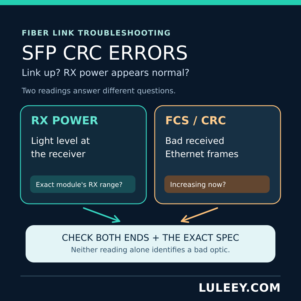
SFP CRC Errors: Confirm They Are New and Received
First, find the exact counter definition for your switch or NIC. Vendors may display CRC, FCS, CRC/Align, input errors and discards as separate fields or aggregates. An increasing FCS/CRC receive counter is the useful clue here; a historic total that stays unchanged is not evidence of a current fault. A discard alone does not establish frame corruption.
Save a baseline for the affected port and the port at the other end. Note the time, traffic level, link events, current counter values and the change after a comparable interval. Do not reset production counters without authorization.
Follow the Direction of the Bad Frames
On a simple duplex link, the first path to examine when B’s receive FCS counter increases is A’s transmitter → the A-to-B fiber path → B’s receiver and host port. Then check the opposite direction separately. This narrows the test, but it does not prove which item is defective: the transmitter, connection, fiber, receiving optic or host-side circuitry can all be candidates.
If only B reports new receive errors, avoid swapping both modules and both patch leads at once. If both ends report them, inspect both directions and any shared change, such as temperature, power, configuration or recent fiber work. Track link resets and, where supported, symbol/PCS errors alongside FCS; do not treat all error counters as interchangeable.
Why Normal RX Power Does Not Clear the Link
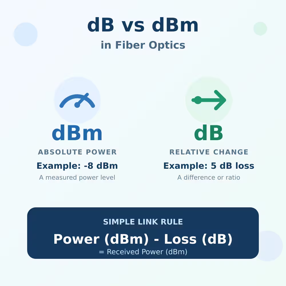
Compare each receiver’s optical reading against the minimum and maximum operating input for its exact module and mode, allowing for diagnostic accuracy and operating conditions. A green dashboard icon or a generic dBm value is not an acceptance test. Check the remote transmitter and local receiver for the same direction; a module’s own TX and RX values belong to opposite directions.
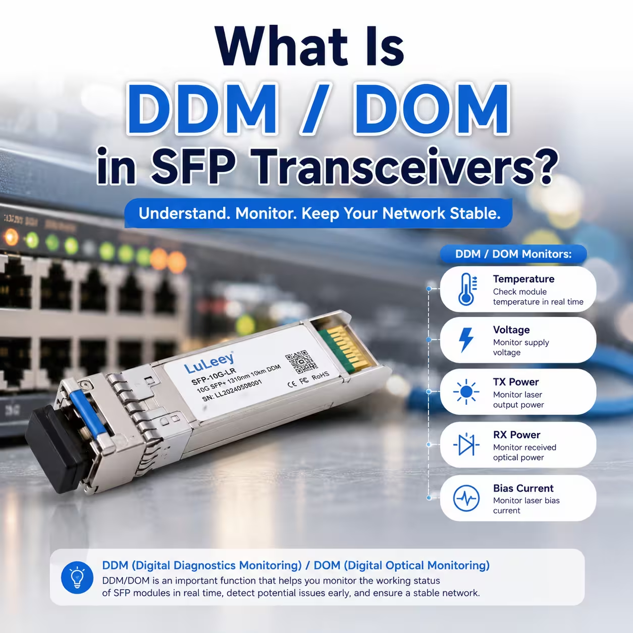
SFF-8472 specifies the diagnostic fields for compatible modules and distinguishes whether the RX value represents average received Optical Power or optical modulation amplitude (OMA). The diagnostic reading is not an Ethernet frame-error test. It also cannot rule out brief impairment between readings, reflection, a damaged or dirty connection, or host-side problems. See LuLeey’s DDM/DOM field guide for the five commonly reported monitor values.
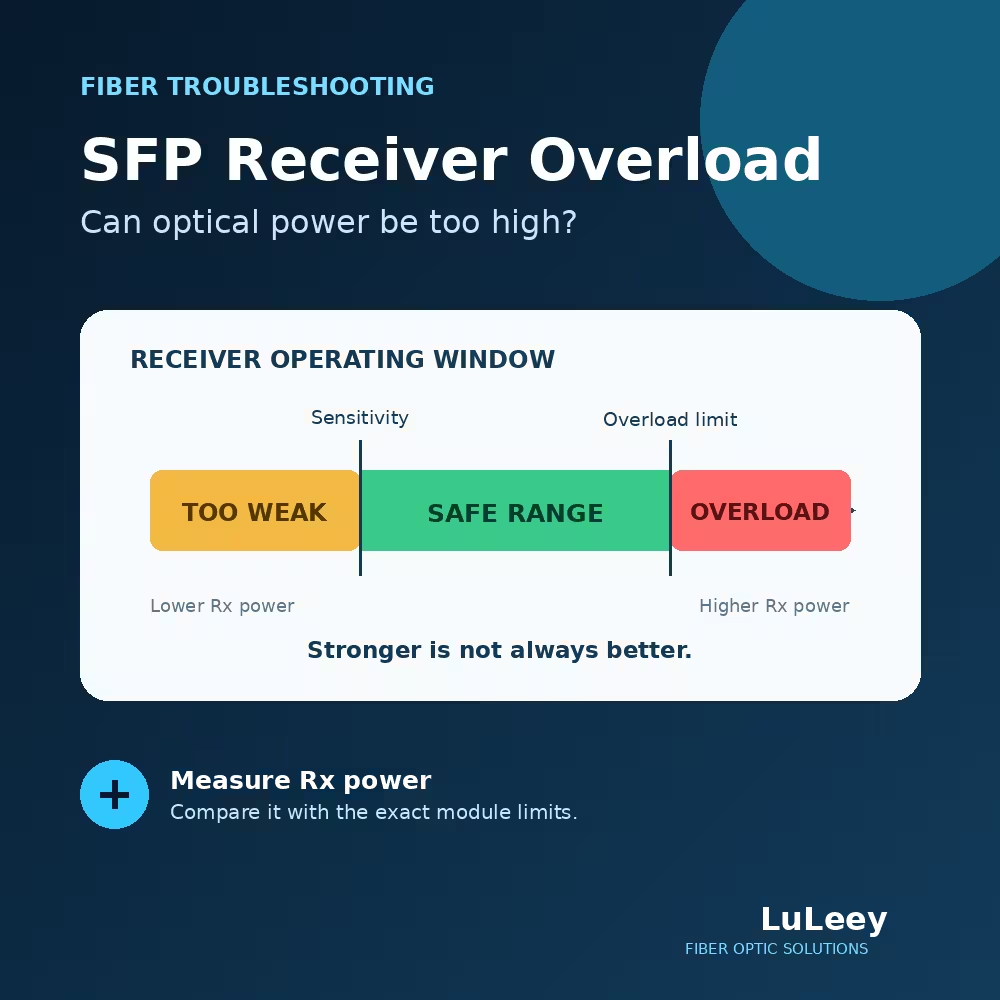
At the other extreme, an unexpectedly strong signal may exceed a receiver’s specified operating maximum. LuLeey’s receiver-overload guide explains how to compare the exact transmitter, path loss and receiver limits. CRC errors alone are not evidence of overload; do not add an arbitrary attenuator.
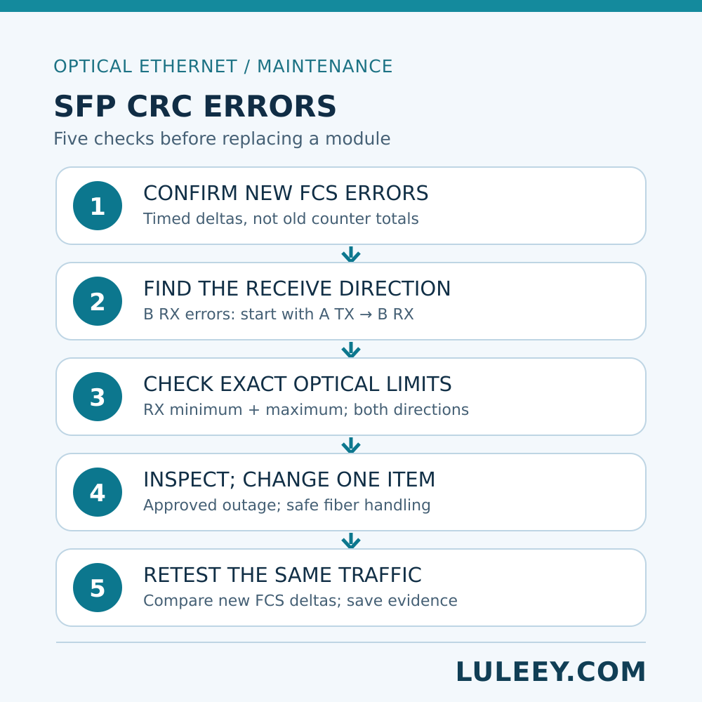
A Controlled Five-Step Check
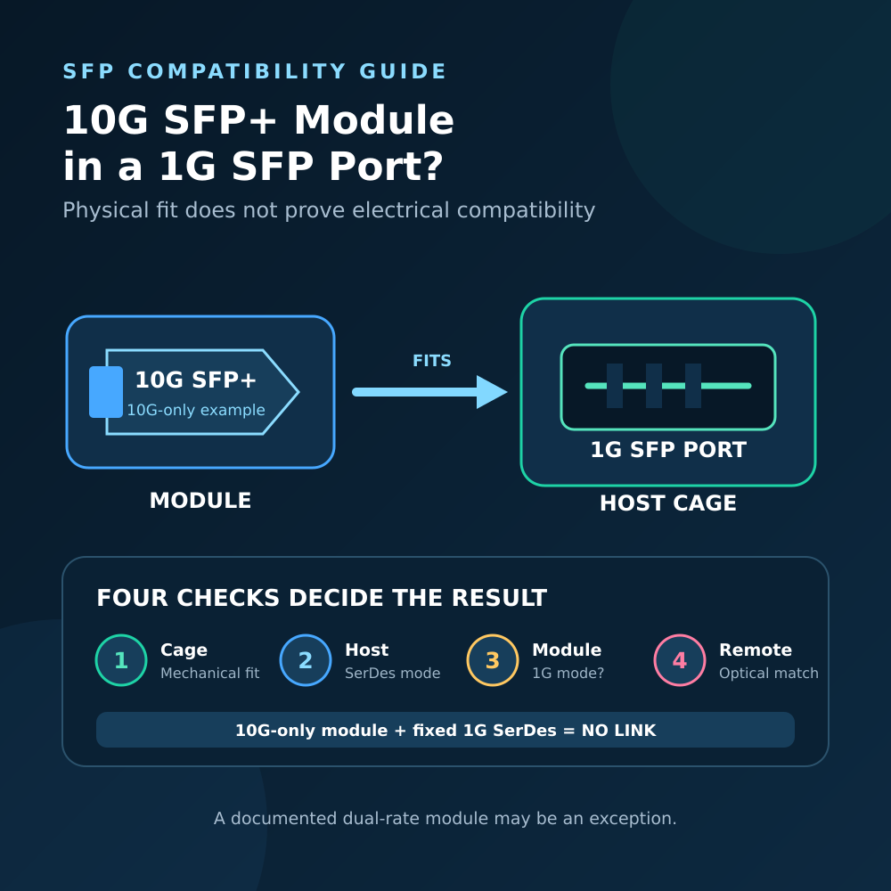
- Record the actual link. Identify both host models and ports, optic part numbers and revisions, module coding, host ASIC/PHY/SerDes mode, firmware, driver, port configuration, actual operating rate and any intermediate patch panel. The SFP or SFP+ label and advertised module rate alone do not establish compatibility or achieved throughput.
- Compare two time-stamped snapshots. Save incoming FCS/CRC, other error counters, link events, DDM RX/TX readings, temperature and traffic at both ends. Decide which receive direction shows new errors.
- Check the intended optics. Verify matched fiber type, wavelengths and transmit/receive pairing, including complementary wavelengths for BiDi optics. Obtain the exact transmitter range and receiver minimum/maximum for each direction. If the upper operating limit is missing, request the complete data sheet; do not assume a short test patch is safe.
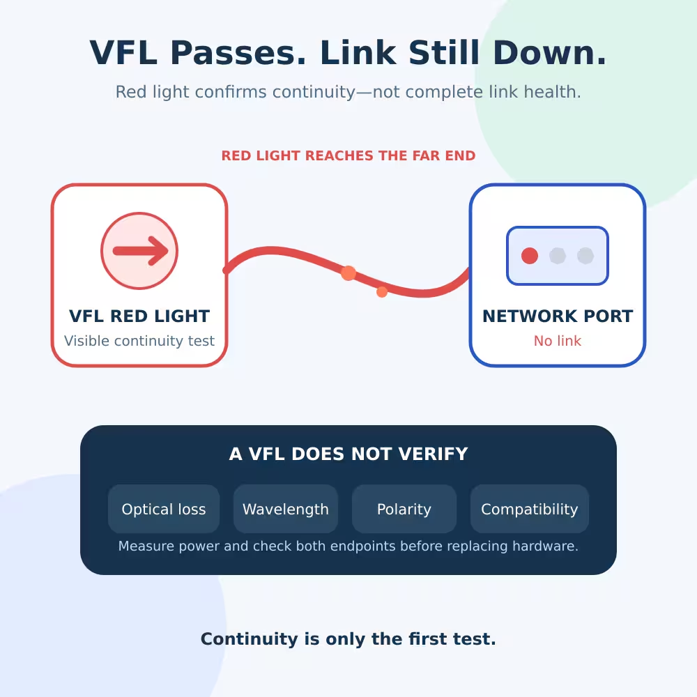
- Inspect before replacing. With the network owner’s approved service procedure, inspect and clean accessible connectors, correct any bend or stressed patch lead, and match the specified connector polish. The Fiber Optic Association’s connector guide explains why contamination and reflectance matter. Never look into an optical port or fiber, and plan for service interruption when opening a live path.
- Change one item and repeat. After documenting the original setup, substitute one known-good, correctly specified patch lead or module in a maintenance window. Recheck RX operating limits before shortening a long-reach optical path. Re-run comparable traffic and compare the increase in the affected receiver’s FCS counter, not just whether its cumulative total is nonzero. Restore or retain changes according to the approved procedure.
If errors follow one optic when it moves to another verified port while everything else is controlled, that strengthens the optic hypothesis; it is still worth confirming host settings and optical conditions. If errors stay on one receiver port, investigate the host port or its configuration. If they stay with a particular fiber run, inspect that run and its termination. These are isolation clues, not universal verdicts.
When Asking LuLeey for a Replacement or Compatibility Check
For example, LuLeey’s LL-SFP-10G-LR product page lists 1310 nm, a duplex LC interface for single-mode fiber, a listed 10 km reach and DDM/DOM. The page publishes a receiver-sensitivity entry but does not publish a receiver overload / maximum operating input value. That page alone is not enough to approve an attenuation setting or a short direct test path. Its multi-brand compatibility wording is not proof for a specific host/firmware combination.
Send the exact host and optic revisions, both-direction counter deltas and DDM readings, measured optical values if available, fiber topology, connector type, firmware/driver, port settings and observed link rate. That gives LuLeey enough information to check a specific replacement rather than guessing from the connector shape.
Next step: take two timed snapshots at both ends. If new FCS Errors are confirmed, identify the receiving direction, verify that receiver’s complete operating window, inspect the relevant path and change only one approved component before retesting.
 SFP/SFP+ (1G/2.5G/5G/10G)
 SFP-T (1G/2.5G/10G)
 AOC Cable 10G/25G/40G/100G
 DAC Cable 10G/25G/40G/100G
 QSFP28 QSFP+ SFP28 100G/40G/25G
 Copper to Fiber Media Converters
 Fiber Media Converter PCBA Board
 OEO Fiber Media Converters
 Serial to Fiber Media Converters
 Video to Fiber Media Converters
 1000M GPON/EPON ONU
 10G EPON ONU/XG-PON/XGS-PON
 2.5G GPON/XPON STICK SFP ONU
 POE GPON/EPON ONU
 Wireless GPON/EPON ONT
 EPON OLT
 GPON OLT
 SFP PON Module
 Industrial Switches
 Managed Switches
 POE Switches
 Unmanaged Switches
 MTP/MPO Fiber Cables
 Fiber Optic Cassettes
 Fiber Optic Loopback
 Optic Cables and Fiber Pigtails
 Optical Splitters and Splitter Box
 Fiber Flange Connectors
 Optical Adapters
 Optical Attenuator
 Quick Connector and Connector Panel
 CATV Amplifier
 CATV Optical Receiver
 Visual Fault Locator
 OTDR
OTDR Optical Power Meter
 Fiber Optic Identifier
 Fiber Optic Cleaners
 Fiber Cleavers & Fiber Strippers
 Copper Tools


