Customs duties are the responsibility of customers, but standard logistics support DDP to most countries, duty-free such as US, DE, UK, CA, FR, IT, PL, AT, JP…





















































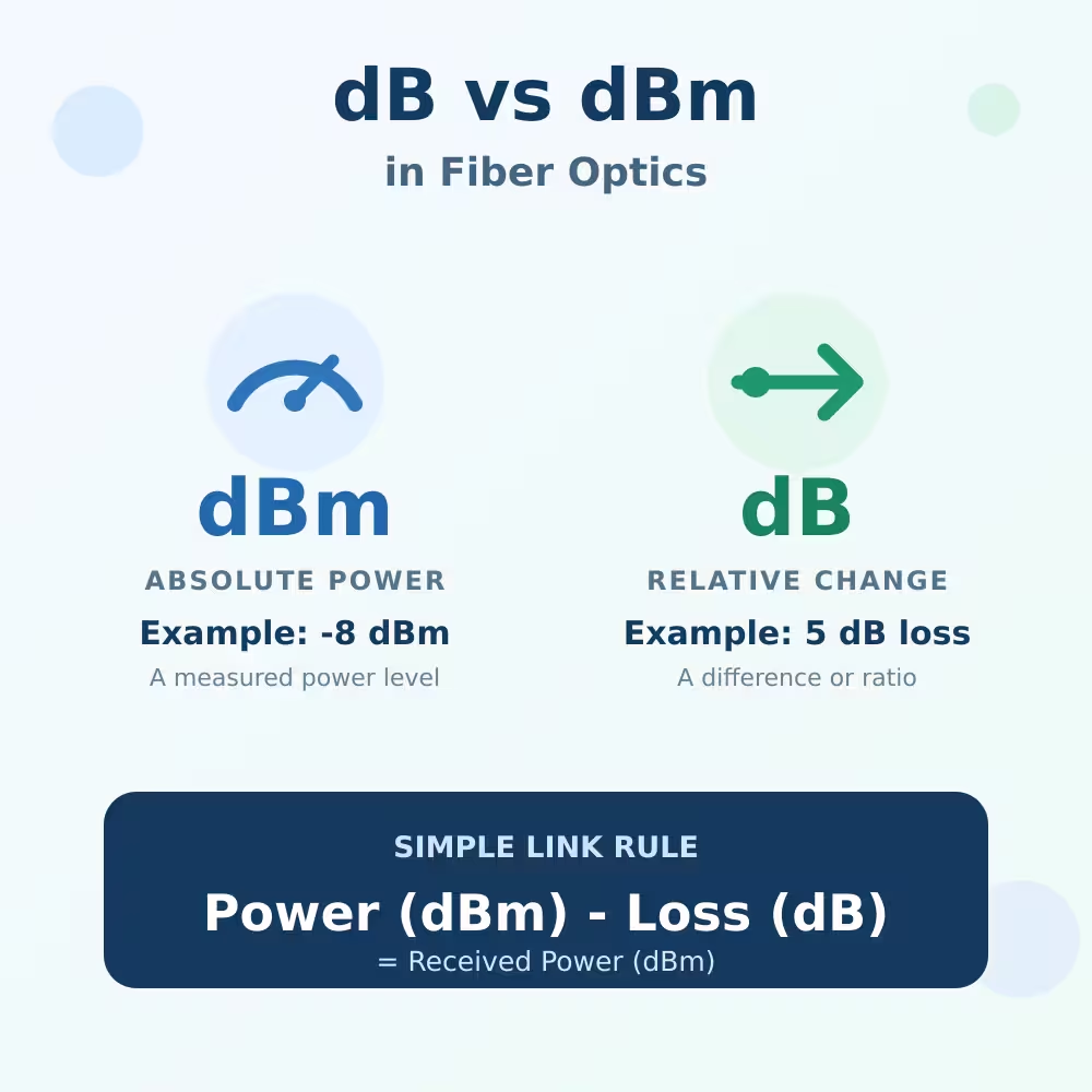
If an optical power meter shows -8 dBm, but a connector or attenuator is rated in dB, what is the difference?
The simplest way to understand dB vs dBm in fiber optics is:
- dBm tells you the actual Optical Power at one point.
- dB tells you how much the power changed between two points.
You can think of dBm as the amount of water currently in a tank, while dB describes how much water was lost between the inlet and outlet.
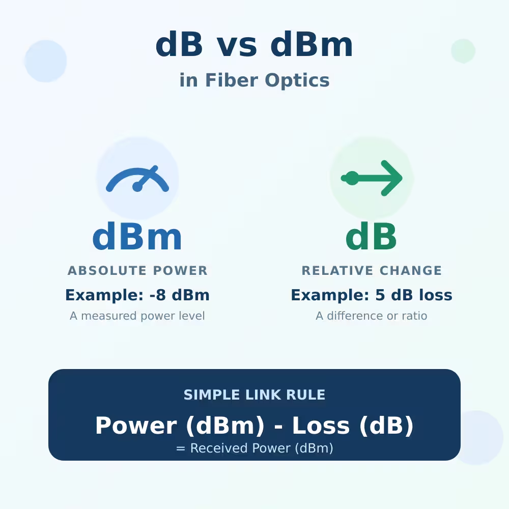
dB vs dBm in Fiber Optics: Quick Comparison
| Unit | What it describes | Common use | Example |
|---|---|---|---|
| dBm | Absolute optical power referenced to 1 milliwatt | TX power, RX power and power-meter readings | RX power = -8 dBm |
| dB | A power ratio, change, gain or loss | Cable loss, splitter loss and attenuator value | Link loss = 5 dB |
Remember this short rule:
Power is measured in dBm. Loss is measured in dB.
The Fiber Optic Association’s power measurement guide gives the same practical distinction: optical power meters normally display power in dBm and relative loss in dB after a reference has been set.
What Does dBm Mean in Fiber Optics?
dBm is an absolute power level referenced to 1 milliwatt.
- 0 dBm = 1 mW
- -3 dBm ≈ 0.5 mW
- -10 dBm = 0.1 mW
- -20 dBm = 0.01 mW
- -30 dBm = 0.001 mW
Negative dBm values are normal in fiber networks. A negative sign does not automatically mean that the connection is faulty.
The important rule is:
The more negative the dBm value, the lower the optical power.
For example:
- -5 dBm is stronger than -15 dBm.
- -15 dBm is stronger than -25 dBm.
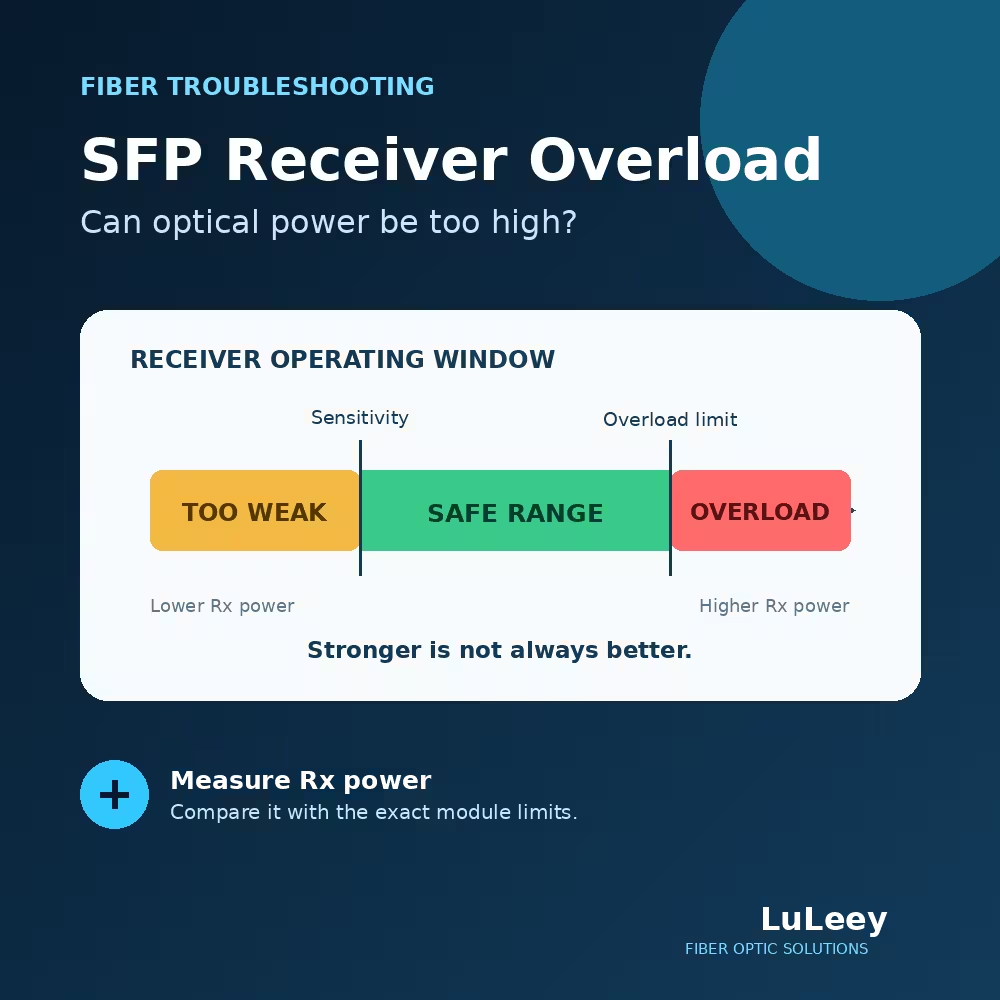
However, stronger is not always better. A receiver can fail when the signal is below its sensitivity limit, but it can also overload when the signal is above its maximum input level.
There is no universal “best dBm value” for every fiber link. Always compare the measured power with the TX or RX range specified for the exact transceiver, ONU, ONT or receiver.
What Does dB Mean in Fiber Optics?
dB describes a ratio or change between two power levels. It does not tell you the actual optical power unless you also know a starting value.
Common examples include:
- fiber attenuation: 2 dB;
- connector and splice loss: 1 dB;
- splitter loss: 7 dB;
- fixed attenuator: 5 dB;
- amplifier gain: 10 dB.
A change of approximately 3 dB means that the power has been halved or doubled, depending on whether it is a loss or gain. A 10 dB loss reduces power to one tenth of the original level.
In normal link-budget calculations, component losses are usually written as positive numbers and subtracted from the starting dBm value.
How to Calculate RX Power from dBm and dB
Use this simple formula when the link contains only passive losses:
Estimated RX power (dBm) = TX power (dBm) − total link loss (dB)
Example
Suppose a transmitter has:
TX power = -2 dBm
The link contains:
- fiber, connectors and splices: 3 dB loss;
- optical attenuator: 3 dB loss.
Total loss:
3 dB + 3 dB = 6 dB
Estimated RX power:
-2 dBm − 6 dB = -8 dBm
The receiver should therefore see approximately -8 dBm.
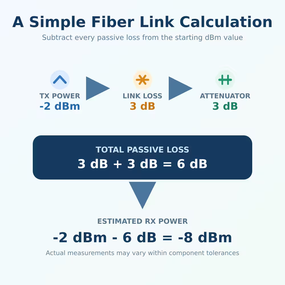
The real reading may be slightly different because transmitter output, component loss and meter accuracy all have tolerances.
The FOA explanation of optical loss math also shows that 3 dB is approximately a factor of two and that lower optical power produces a more negative dBm reading. The relationship between dBm and milliwatt power is also documented in ITU-T G.650.2.
How to Use dB and dBm on an Optical Power Meter
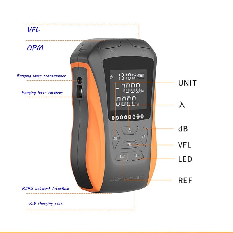
Many optical power meters can display both dBm and dB.
Use dBm to measure actual power
Select dBm when you want to check:
- transmitter output power;
- received optical power;
- ONU or ONT input power;
- SFP or SFP+ optical signal level;
- power before or after an attenuator.
Set the meter to the wavelength being measured. A reading taken with the wrong wavelength setting may not be accurate because optical power meters use wavelength-dependent calibration.
Use dB to measure relative loss
Select dB when you want to compare a measured value with a reference.
For example:
- Measure the source through a known-good reference cable.
- Set that reading as the reference or zero value.
- Add the cable or component being tested.
- Read the additional loss in dB.
The reference must be set correctly. Switching the meter to dB without establishing a valid reference does not automatically produce a meaningful loss measurement.
Can You Convert dB Directly to dBm?
No. You need a starting power level.
For example, a 5 dB loss does not tell you the final dBm value by itself.
- Starting at 0 dBm: 0 dBm − 5 dB = -5 dBm.
- Starting at -10 dBm: -10 dBm − 5 dB = -15 dBm.
The same 5 dB loss produces different final power levels because the starting powers are different.
How Does an Optical Attenuator Change dBm?
An optical attenuator introduces a controlled amount of loss.
If the measured power is -4 dBm and you add a 5 dB attenuator:
-4 dBm − 5 dB = approximately -9 dBm
This calculation helps when selecting an attenuator to keep the receiver below its maximum input power.
Do not choose an attenuator only from a target number found online. First check:
- actual measured power;
- receiver overload limit;
- receiver sensitivity;
- existing link loss;
- attenuator wavelength and connector type.
LuLeey offers fixed and adjustable optical attenuators for different connector and loss requirements.
Can You Calculate Link Loss from SFP DDM Readings?
Sometimes, but use the correct values.
For one transmission direction, compare:
Remote module TX power → Local module RX power
Do not normally subtract the local module’s own TX power from its own RX power. Those readings represent opposite transmission directions and may travel through different fibers, connectors or optical paths.
DDM readings also have accuracy limits. They are useful for monitoring and troubleshooting, but an independently calibrated optical power meter may be more appropriate for formal loss testing.
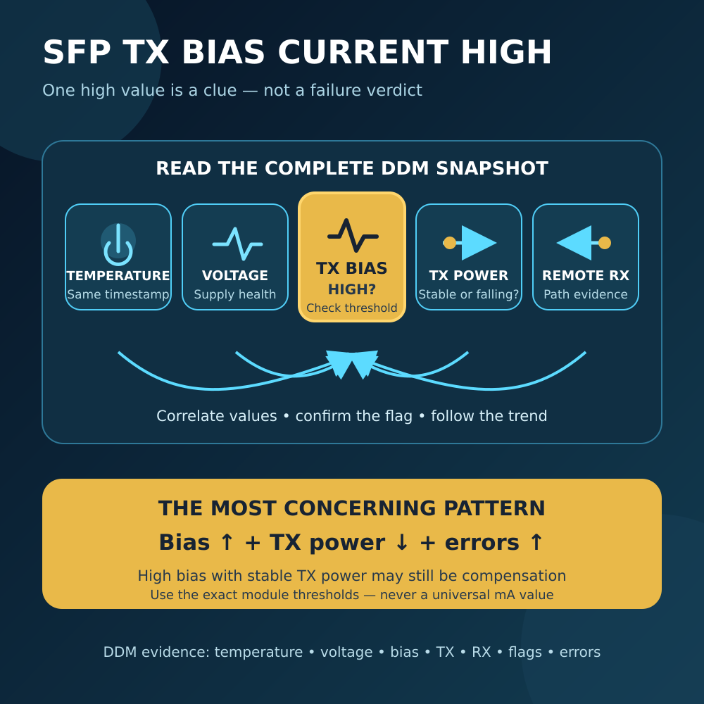
Read What Is DDM / DOM in SFP Transceivers? for an explanation of TX power, RX power, temperature and other diagnostic values.
Common dB and dBm Mistakes
Mistake 1: Thinking -20 dBm is stronger than -5 dBm
It is weaker. -20 dBm represents less optical power than -5 dBm.
Mistake 2: Adding passive loss to the dBm value
If a passive link adds 4 dB of loss, subtract 4 dB from the starting dBm value.
Mistake 3: Treating dB as an absolute power level
A value such as 5 dB describes a change. It does not tell you the final optical power without a starting dBm value.
Mistake 4: Looking for one universal good RX value
Different GPON, XGS-PON, SFP, SFP+ and long-distance optical receivers use different power ranges. Compare the reading with the exact equipment specification.
Mistake 5: Using the wrong wavelength setting
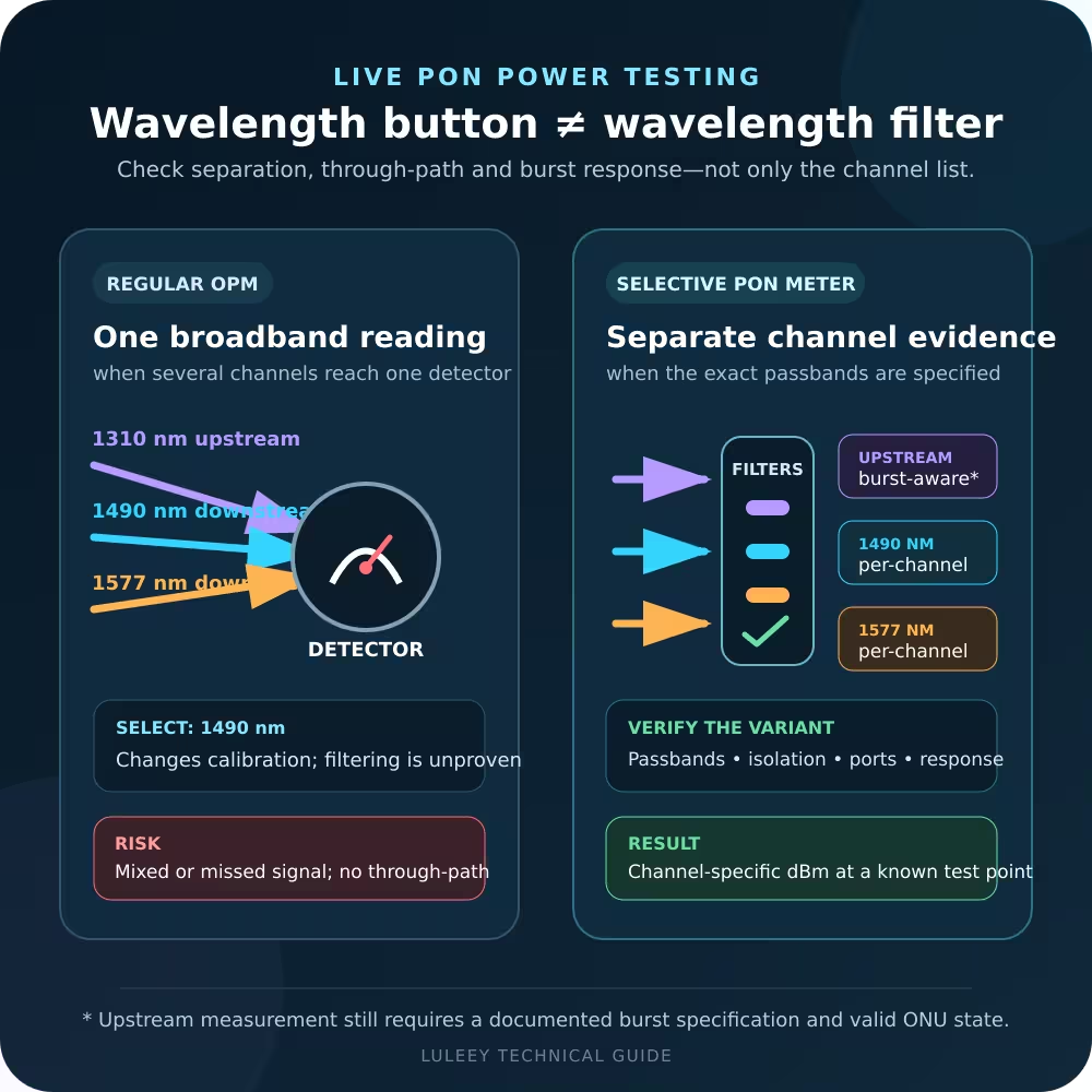
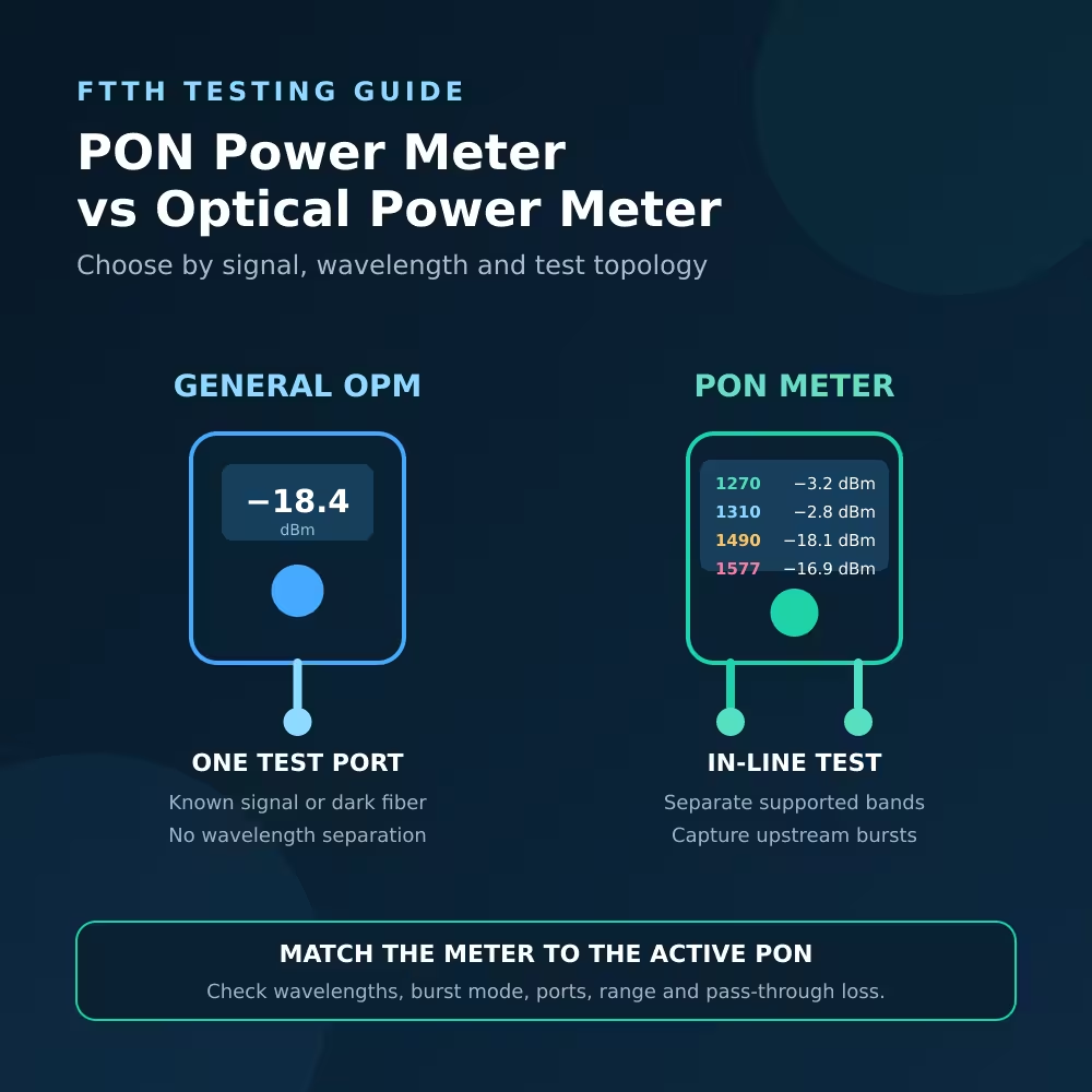
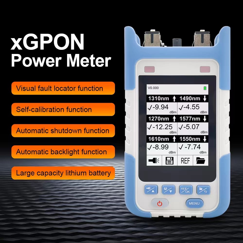
Select the measurement wavelength that matches the signal. For live PON testing, use a meter designed for the required PON wavelengths and measurement method.
Final Answer
The difference between dB and dBm in fiber optics is simple:
- dBm = actual optical power at one point
- dB = power change, gain or loss between two points
To estimate the received power, subtract link loss in dB from transmitter power in dBm:
TX power (dBm) − link loss (dB) = RX power (dBm)
When testing a real fiber link, use the correct wavelength, establish a proper reference for loss measurements, and compare the final reading with the exact receiver specification.
If you need to measure optical power or controlled attenuation, review LuLeey’s optical power meters and optical attenuators based on the connector type, wavelength and measurement range required by your link.
 SFP/SFP+ (1G/2.5G/5G/10G)
 SFP-T (1G/2.5G/10G)
 AOC Cable 10G/25G/40G/100G
 DAC Cable 10G/25G/40G/100G
 QSFP28 QSFP+ SFP28 100G/40G/25G
 Copper to Fiber Media Converters
 Fiber Media Converter PCBA Board
 OEO Fiber Media Converters
 Serial to Fiber Media Converters
 Video to Fiber Media Converters
 1000M GPON/EPON ONU
 10G EPON ONU/XG-PON/XGS-PON
 2.5G GPON/XPON STICK SFP ONU
 POE GPON/EPON ONU
 Wireless GPON/EPON ONT
 EPON OLT
 GPON OLT
 SFP PON Module
 Industrial Switches
 Managed Switches
 POE Switches
 Unmanaged Switches
 MTP/MPO Fiber Cables
 Fiber Optic Cassettes
 Fiber Optic Loopback
 Optic Cables and Fiber Pigtails
 Optical Splitters and Splitter Box
 Fiber Flange Connectors
 Optical Adapters
 Optical Attenuator
 Quick Connector and Connector Panel
 CATV Amplifier
 CATV Optical Receiver
 Visual Fault Locator
 OTDR
OTDR Optical Power Meter
 Fiber Optic Identifier
 Fiber Optic Cleaners
 Fiber Cleavers & Fiber Strippers
 Copper Tools


