Customs duties are the responsibility of customers, but standard logistics support DDP to most countries, duty-free such as US, DE, UK, CA, FR, IT, PL, AT, JP…





















































The main difference in PON Power Meter vs optical power meter testing is not simply the number of wavelengths printed on the case. A general optical power meter measures optical power arriving at one test port. A suitable PON power meter uses wavelength-selective filters and, in many models, an in-line connection so it can separate PON signals and measure upstream burst power while the OLT and ONT remain connected.
Use a general optical power meter for dark-fiber loss testing with a known source, or for checking one known optical signal at a test point. Use a PON power meter when you need to identify separate upstream and downstream levels on an active GPON or XGS-PON link.
The exact answer still depends on the meter. Some products called “PON meters” support only certain wavelengths or downstream measurements. Always check the port arrangement, supported PON generations, burst-measurement capability and pass-through insertion loss.
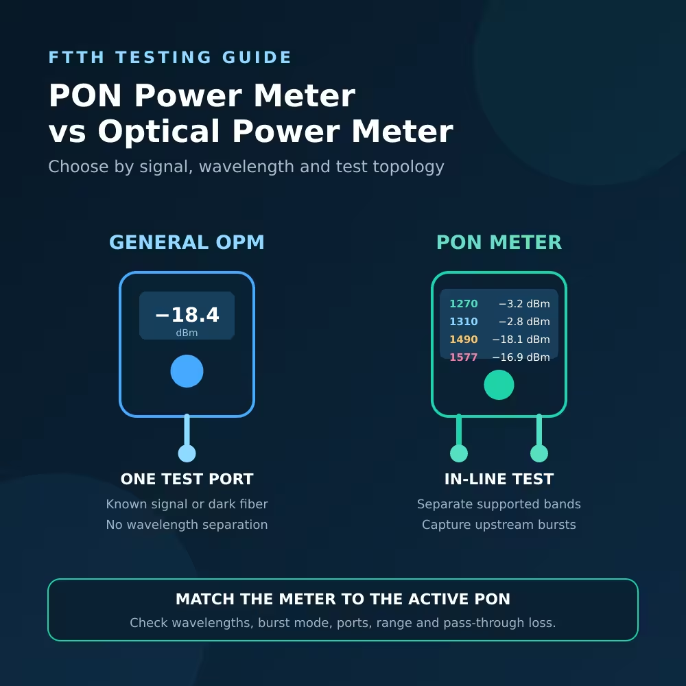
PON Power Meter vs Optical Power Meter at a Glance
| Question | General optical power meter | PON power meter |
|---|---|---|
| Measures absolute power in dBm | Yes | Yes |
| Dark-fiber loss test with a separate source | Yes | Sometimes, if a general OPM mode is included |
| Separates simultaneous PON wavelengths | Usually no | Yes, for supported wavelengths |
| Measures upstream ONU/ONT burst power | Usually no | Yes, if burst measurement is specified |
| Tests in line while service stays connected | Usually no | Often yes, with OLT and ONT pass-through ports |
| Displays pass/fail thresholds | Model-dependent | Common, but thresholds must be configured |
| Suitable for every GPON and XGS-PON network | No | No—wavelengths, range and topology must match |
Neither tool is automatically better. The right tool is the one that measures the required signal without hiding another wavelength or interrupting the condition that creates the signal.
What a General Optical Power Meter Measures
A general optical power meter contains a calibrated detector. You select a calibration wavelength, connect the fiber and read the total optical power that reaches the detector, normally in dBm.
It is useful for:
- Measuring a known transmitter output
- Checking downstream power at an ONT location after disconnecting the ONT
- Testing a dark cable with a compatible light source
- Measuring insertion loss after establishing a valid reference
- Checking Ethernet transceivers and other single-wavelength links
- Comparing optical levels before and after a passive component
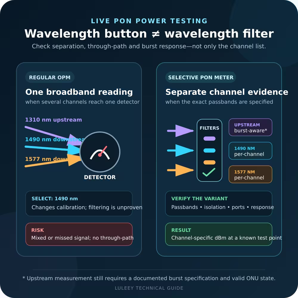
However, changing the wavelength setting does not turn a broadband detector into a wavelength separator. The setting applies the instrument’s calibration for that wavelength.
If several live optical signals reach a non-selective detector simultaneously, the display does not necessarily show the independent power of each signal.
A one-port measurement also terminates the optical path at the meter. The ONT is disconnected, so it may lose registration. In a scheduled PON upstream, an ONU normally transmits in bursts according to grants from the OLT. Once the link is broken, the condition needed for a meaningful upstream measurement may disappear.
What a PON Power Meter Measures
A suitable in-line PON power meter is placed between the optical distribution network and the subscriber ONT or ONU:
OLT and ODN → PON power meter → ONT or ONU
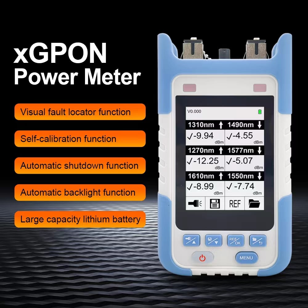
Inside the instrument, optical filters and couplers separate supported wavelength bands. The pass-through path allows both network endpoints to stay optically connected while the meter samples the downstream and upstream signals.
This design can provide:
- Wavelength-selective downstream readings
- Upstream burst-power measurement
- Simultaneous or near-simultaneous display of supported PON bands
- Pass/fail evaluation against configured thresholds
- Service activation checks without replacing the OLT with a test source
The meter adds some insertion loss because light passes through internal optical components. Check the specified pass-through loss and consider it when a link is already close to its power limit.
Do not assume every instrument with “PON” in its name has two pass-through ports or supports burst power. Verify the exact model and selected version.
Match the Meter to GPON or XGS-PON Wavelengths
The PON generation matters because the upstream and downstream bands are different.
| System | Common nominal upstream | Common nominal downstream | Optional or additional band |
|---|---|---|---|
| GPON | 1310nm | 1490nm | 1550nm may be used for video overlay |
| XGS-PON | 1270nm | 1577nm | Deployment-dependent additional bands may exist |
GPON physical-layer requirements are defined in ITU-T G.984.2, while XGS-PON is specified in ITU-T G.9807.1.
A three-wavelength GPON meter designed for 1310/1490/1550nm does not automatically measure 1270/1577nm XGS-PON correctly.
Likewise, a simple meter calibrated at 1550nm should not be treated as a wavelength-selective 1577nm meter merely because the two numbers look close.
For construction loss testing on an inactive cable, an operator-approved nearby test wavelength may sometimes be used. That is different from measuring the actual live XGS-PON downstream signal at 1577nm. Follow the network’s acceptance procedure and instrument specification.
When a General Optical Power Meter Is Enough
Testing a dark fiber with a known source
Before service activation, connect a stable test source at one end and a general optical power meter at the other. Establish the required reference first if the goal is insertion loss in dB.
The Fiber Optic Association explains that PON cable-plant loss testing uses a source, power meter and reference cables, with measurements made at the wavelengths required by the system. See the FOA guide to testing FTTH PON networks.
Checking one downstream signal at the subscriber point
If only one known downstream service is present and temporarily disconnecting the ONT is allowed, a compatible general meter can measure the power arriving at that point.
This provides one absolute power reading. It does not show whether the ONT is transmitting upstream, registered with the OLT or correctly provisioned.
Testing a normal Ethernet optical link
For a duplex Ethernet link, a general meter can check transmitter output or receiver-side power at the operating wavelength. Compare the result with the exact transceiver specification.
When You Need a PON Power Meter
Measuring ONU or ONT upstream burst power
GPON and XGS-PON upstream transmission is burst-based. The meter must be designed to detect and measure those bursts.
A conventional average-power meter may show an unstable, low or meaningless result.
Separating GPON and XGS-PON signals
When multiple PON generations share an optical distribution network, a broadband detector cannot reliably identify how much power comes from each wavelength.
Use a wavelength-selective meter supporting every band that must be measured.
Testing without taking the subscriber offline
An in-line meter allows the ONT to remain connected to the OLT. This preserves registration and upstream scheduling, subject to the meter’s supported topology and insertion-loss specification.
Applying operator-specific thresholds
Many PON meters display pass, warning or fail results. This is useful only when the correct thresholds have been loaded.
A green result based on generic factory thresholds is not proof that the link meets a particular operator’s requirements.
How to Perform a Live PON Optical Power Test
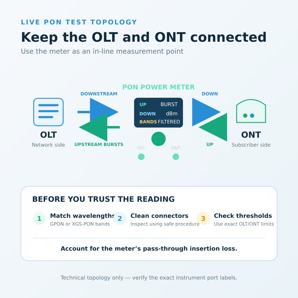
Step 1: Identify the PON system
Confirm whether the service is GPON, EPON, XG-PON, XGS-PON or a coexistence deployment.
Do not infer the protocol from the connector color or advertised subscriber speed.
Step 2: Check the instrument specification
Verify:
- Supported upstream and downstream wavelengths
- Upstream burst-mode capability
- OLT and ONT pass-through ports
- Measurement range and uncertainty
- Pass-through insertion loss
- Connector type and polish
- Required threshold and data-storage functions
Step 3: Follow optical-safety procedures
Never look into a fiber, adapter, transceiver or meter port. Treat an unknown fiber as active until verified safe using the approved procedure.
Step 4: Inspect and clean
After confirming that inspection is safe, inspect and clean the connectors. Contamination can add loss and may transfer from a dirty patch lead to the meter or ONT port.
Step 5: Insert the meter in the correct direction
Connect the network side to the meter’s OLT port and the subscriber device to its ONT or ONU port.
Do not reverse the ports unless the instrument documentation explicitly permits it.
Step 6: Allow the ONT to register
Wait for the ONT to regain its normal PON state. Upstream burst measurement depends on an active relationship with the OLT.
If registration does not return, check patching, connectors, meter direction and pass-through loss before trusting the readings.
Step 7: Read every required wavelength
Record upstream and downstream results separately. On a coexistence network, confirm that the displayed labels correspond to the actual GPON or XGS-PON bands.
Step 8: Compare with exact limits
Use the operator’s approved thresholds and exact OLT/ONT optical specifications.
Check both receiver sensitivity and overload. There is no universal “good dBm” value for all PON equipment.
Step 9: Restore the final connection
Remove the meter, clean as required, reconnect the ONT and confirm that the service operates normally.
Record the test point, instrument, wavelength, date and result.
Common Measurement Mistakes
Mistake 1: Selecting 1490nm and assuming the meter isolates 1490nm
On a general optical power meter, wavelength selection normally changes calibration. It does not necessarily filter out 1550nm or 1577nm light.
Mistake 2: Measuring ONU upstream with the ONT disconnected
The ONU may not transmit normal scheduled bursts when it is no longer connected to the OLT. Use a correctly connected in-line meter with specified burst capability.
Mistake 3: Using a GPON-only meter after an XGS-PON upgrade
A 1310/1490/1550nm meter does not automatically support 1270/1577nm. Check the exact wavelength table.
Mistake 4: Treating dBm as link loss
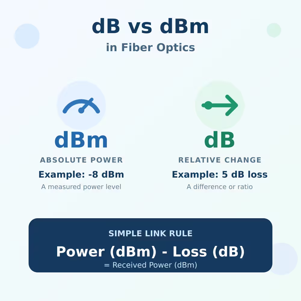
dBm is absolute power at a point. Link loss in dB requires a valid reference or known launch level.
One receiver reading alone does not show where the loss occurred.
Mistake 5: Trusting pass/fail without checking thresholds
Pass/fail is only as accurate as the configured limits. Confirm the correct operator profile and measurement band.
Mistake 6: Ignoring meter insertion loss
An in-line PON meter consumes part of the optical budget. On a marginal link, inserting the meter can affect registration or service stability.
Choosing a LuLeey Meter by Test Scenario
For established GPON systems using 1310/1490/1550nm, LuLeey’s in-line GPON power meter lists synchronous three-wavelength measurement and 1310nm burst-mode testing.
Its page specifies less than 1.5dB pass-through insertion loss and optional general OPM/VFL functions.
For networks that may include GPON and XGS-PON bands, review the selectable versions of LuLeey’s 10G XGS-PON optical power meter.
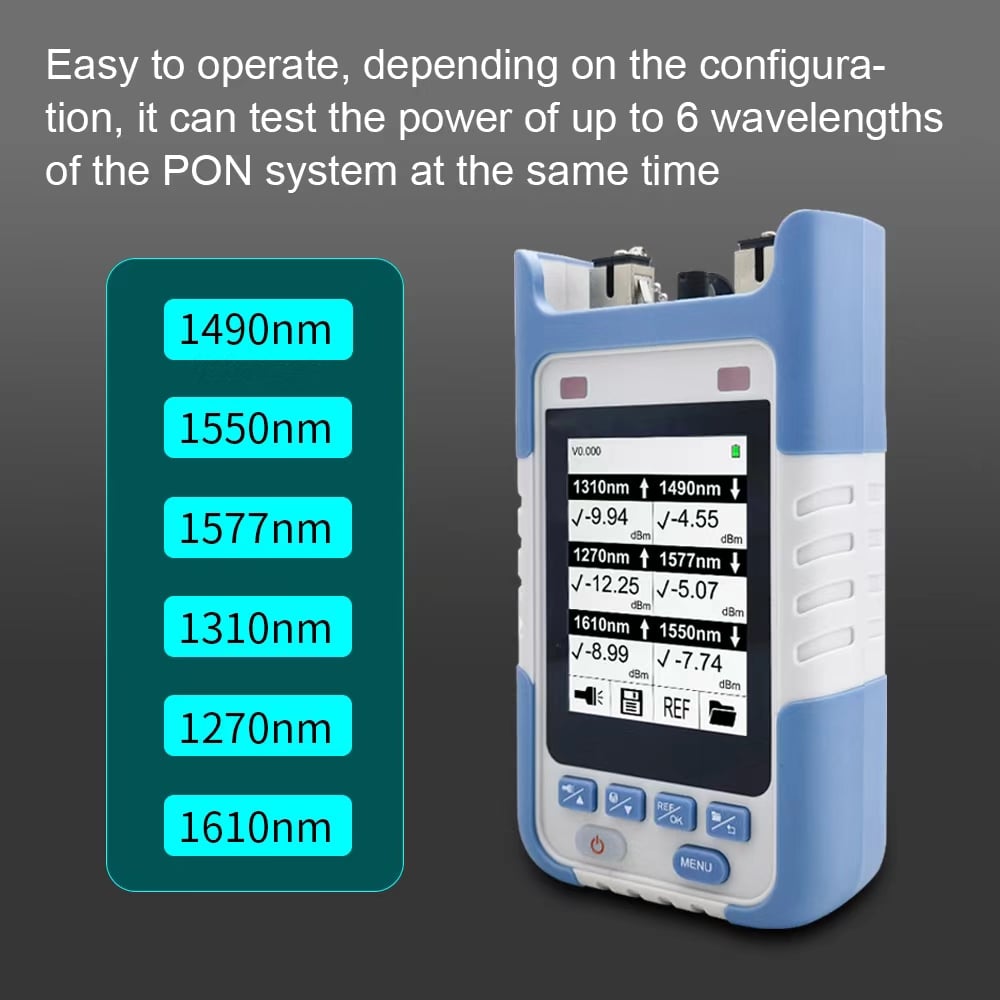
The page lists versions covering combinations of 1310, 1490, 1550, 1270, 1577 and 1610nm. The exact connector and wavelength set depends on the selected version.
Do not choose from the product title alone. Before ordering, confirm:
- Required wavelengths
- Whether testing must be performed in line
- Upstream burst-measurement requirement
- Connector polish
- Measurement range
- Exact meter version
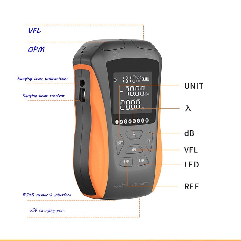
The broader optical power meter and VFL category can be used to compare general and PON-oriented testers by job type.
Final Answer
The practical answer to PON power meter vs optical power meter is:
- Choose a general optical power meter for dark-fiber loss testing with a known source, or for one known optical signal where disconnecting the receiver is acceptable.
- Choose a wavelength-selective PON power meter for live GPON or XGS-PON Testing, separate upstream/downstream readings and burst-mode ONU measurements.
Before selecting a meter, write down the PON technology, wavelengths, connector polish, expected power range, whether service must stay connected and whether upstream burst power must be measured.
When asking LuLeey to confirm a model, provide the OLT and ONT models together with the active wavelength plan. This allows the exact meter version to be checked instead of relying on a generic “GPON” or “10G PON” label.

 SFP/SFP+ (1G/2.5G/5G/10G)
 SFP-T (1G/2.5G/10G)
 AOC Cable 10G/25G/40G/100G
 DAC Cable 10G/25G/40G/100G
 QSFP28 QSFP+ SFP28 100G/40G/25G
 Copper to Fiber Media Converters
 Fiber Media Converter PCBA Board
 OEO Fiber Media Converters
 Serial to Fiber Media Converters
 Video to Fiber Media Converters
 1000M GPON/EPON ONU
 10G EPON ONU/XG-PON/XGS-PON
 2.5G GPON/XPON STICK SFP ONU
 POE GPON/EPON ONU
 Wireless GPON/EPON ONT
 EPON OLT
 GPON OLT
 SFP PON Module
 Industrial Switches
 Managed Switches
 POE Switches
 Unmanaged Switches
 MTP/MPO Fiber Cables
 Fiber Optic Cassettes
 Fiber Optic Loopback
 Optic Cables and Fiber Pigtails
 Optical Splitters and Splitter Box
 Fiber Flange Connectors
 Optical Adapters
 Optical Attenuator
 Quick Connector and Connector Panel
 CATV Amplifier
 CATV Optical Receiver
 Visual Fault Locator
 OTDR
OTDR Optical Power Meter
 Fiber Optic Identifier
 Fiber Optic Cleaners
 Fiber Cleavers & Fiber Strippers
 Copper Tools


