Customs duties are the responsibility of customers, but standard logistics support DDP to most countries, duty-free such as US, DE, UK, CA, FR, IT, PL, AT, JP…





















































Fiber Optic Splitter Loss is not the number printed after “1:”. A 1:8 splitter does not have an ideal loss of 8dB. Because the input power is divided equally among eight outputs, its ideal loss is about 9.03dB per output. A real splitter has additional loss, so its specified maximum insertion loss will be higher.
This guide shows the ideal loss from 1:2 to 1:64, explains why real values are higher, and gives a practical method for adding splitter loss to an FTTH or PON link budget.
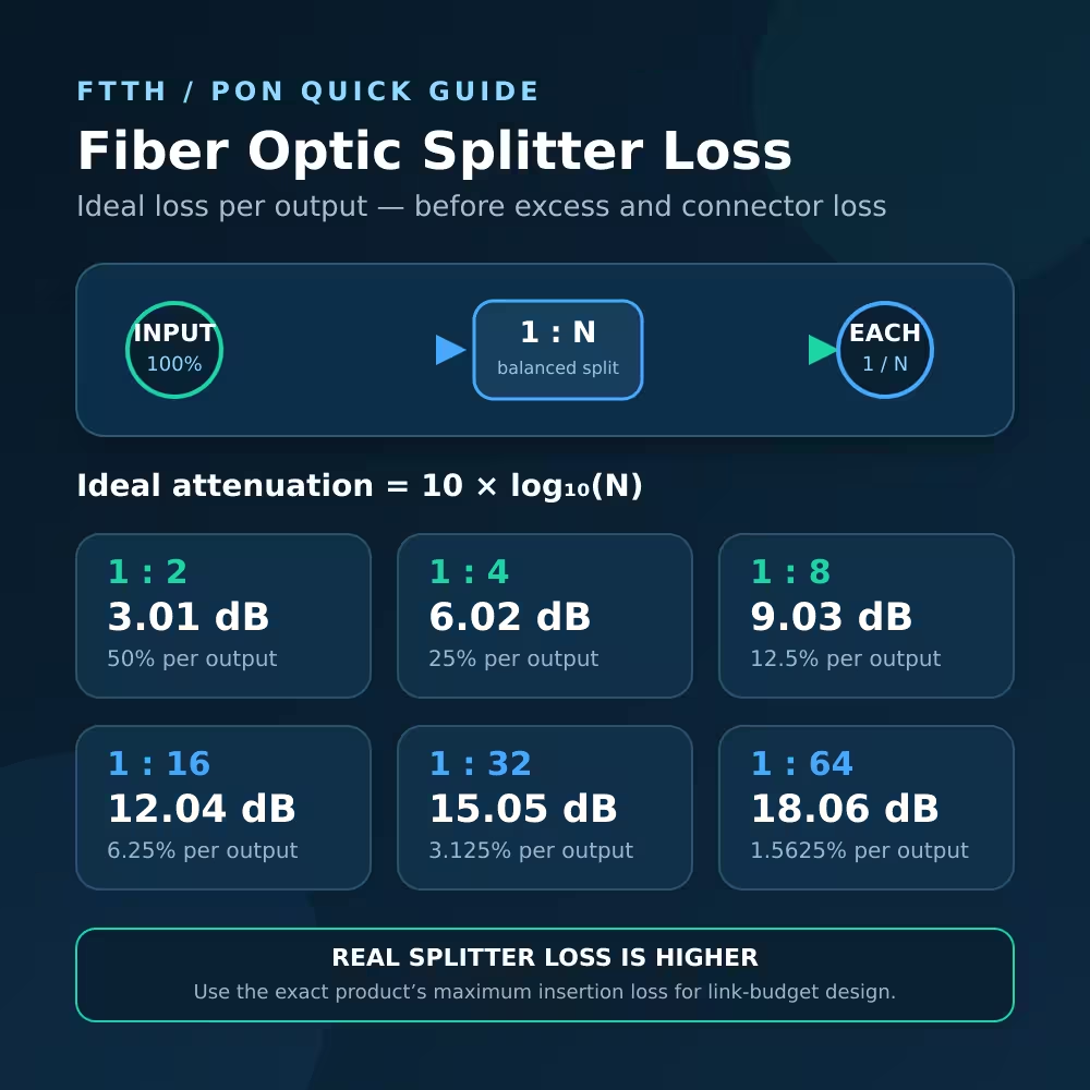
Fiber Optic Splitter Loss Formula
For a balanced 1:N splitter, each output ideally receives 1/N of the input optical power.
The ideal attenuation magnitude is:
Ideal splitter loss (dB) = 10 × log10(N)
For example, a 1:8 splitter has eight equal outputs:
10 × log10(8) = 9.03dB
If the optical power entering an ideal 1:8 splitter is 0dBm, each output would be approximately −9.03dBm before considering excess loss, connectors or manufacturing tolerance.
In power-ratio notation, the change is 10 × log10(1/N), which is negative. In a link budget, attenuation is normally written as a positive loss value and subtracted from the transmitter power.
Fiber Optic Splitter Loss Table: 1:2 to 1:64
| Split ratio | Ideal power per output | Exact ideal loss | Rounded ideal loss | FOA example typical insertion loss* |
|---|---|---|---|---|
| 1:2 | 50% | 3.01dB | 3dB | 3.6dB |
| 1:4 | 25% | 6.02dB | 6dB | 6.8dB |
| 1:8 | 12.5% | 9.03dB | 9dB | 10.0dB |
| 1:16 | 6.25% | 12.04dB | 12dB | 13.0dB |
| 1:32 | 3.125% | 15.05dB | 15dB | 16.0dB |
| 1:64 | 1.5625% | 18.06dB | 18dB | 19.5dB |
*The typical insertion-loss column is an educational example published by the Fiber Optic Association. It is not a universal specification. Use the maximum insertion loss from the datasheet of the exact splitter being installed.
One useful shortcut is that every doubling of the output count adds approximately 3.01dB of ideal loss:
- 1:8 to 1:16: about 3.01dB more
- 1:16 to 1:32: about 3.01dB more
- 1:32 to 1:64: about 3.01dB more
This is why adding spare output capacity is not optically free.
Why Actual Splitter Loss Is Higher Than the Formula
The formula describes perfect power division. A manufactured splitter also has component loss and production tolerances.
Excess loss
Some optical power is lost inside the component rather than reaching an output. The difference between ideal division loss and measured insertion loss includes this inefficiency and other construction-related effects.
Port-to-port uniformity
The output ports are not perfectly identical. Loss uniformity describes the difference between the strongest and weakest output ports. The weakest permitted port is important when checking the worst-case link budget.
Connectorized or bare-fiber construction
A connectorized splitter may include connector-related loss in its published insertion-loss value, but specification methods can differ. Confirm whether the datasheet value applies to the complete terminated assembly or only the splitter component.
Wavelength, temperature and tolerance
Insertion loss can vary with operating wavelength, temperature and manufacturing tolerance. Use the guaranteed specification across the wavelengths and environmental range required by the network.
ITU-T G.671 defines transmission parameters for passive optical components, including insertion loss and loss variation, but it does not create one universal insertion-loss value for every commercial 1:N splitter. The finished product specification remains essential.
Ideal Loss vs LuLeey PLC Splitter Specifications
The difference becomes clearer when theoretical values are compared with specific finished products:
| Splitter | Ideal loss | Verified maximum insertion loss |
|---|---|---|
| 1×8 SC/APC PLC splitter | 9.03dB | ≤10.7dB |
| 1×16 SC/UPC PLC splitter | 12.04dB | ≤14.0dB |
| 1×32 SC/APC PLC splitter | 15.05dB | ≤17.3dB |
These values apply to the specific package and connector versions shown on those pages. Another splitter type, connector option or production specification may have a different maximum loss.
For engineering, use the verified maximum insertion loss—not the ideal number and not an attractive “typical” value.
How Cascaded Splitters Affect Loss
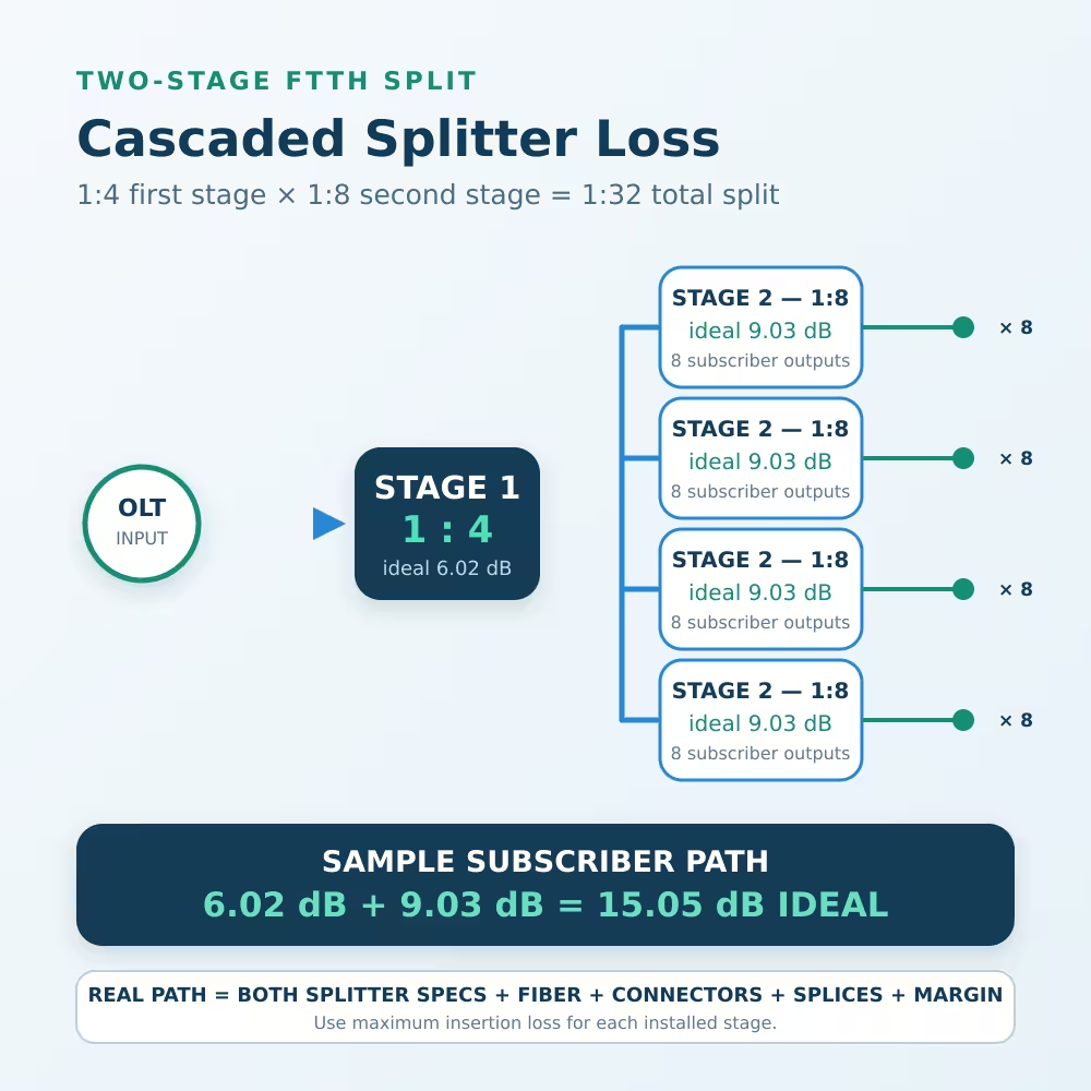
Splitters are often installed in two stages. For example:
1:4 first stage × 1:8 second stage = 1:32 total split
The ideal splitter loss is additive:
6.02dB + 9.03dB = 15.05dB
That equals the ideal loss of a single 1:32 splitter because both designs divide the original input power among 32 outputs.
The real cascaded path can be different. Each splitter has its own maximum insertion loss, and the connection between the two stages may add adapters, connectors, splices and fiber. Calculate the loss through the exact path to the subscriber rather than multiplying a generic value.
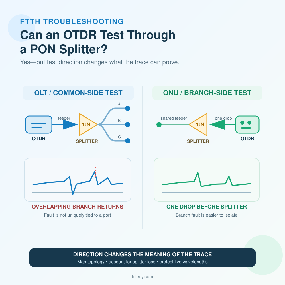
If only one output of the first-stage splitter feeds the second stage, the second-stage loss affects only subscribers on that branch. Draw the actual route before adding components.
How to Add Splitter Loss to an FTTH Link Budget
Use this structure:
Total planned loss = splitter loss + fiber loss + connector loss + splice loss + other passive loss + engineering margin
Example assumptions for one path:
| Item | Example value |
|---|---|
| 1×32 splitter maximum insertion loss | 17.3dB |
| Fiber attenuation for the route and wavelength | 2.2dB |
| Connector and adapter allowance | 1.0dB |
| Splice allowance | 0.5dB |
| Engineering margin | 3.0dB |
| Total planned loss | 24.0dB |
These numbers are only an example. Fiber attenuation changes with wavelength, while connector counts, splice quality and required margin vary by project.
After calculating the planned loss, estimate receiver power:
Estimated RX power (dBm) = minimum TX power (dBm) − total planned loss (dB)
Compare that result with the receiver sensitivity and overload limits of the exact OLT, ONU, ONT or optical module. There is no single acceptable optical-power range for every GPON, xgs-pon or Ethernet system.
If dB and dBm are still confusing, read dB vs dBm in Fiber Optics.
How to Choose the Split Ratio
1. Count the required outputs
Choose enough outputs for the current subscribers and realistic expansion. Do not select a larger ratio only because it offers more ports; each doubling costs about 3.01dB of ideal optical budget.
2. Calculate every splitter stage
For cascaded designs, add the maximum insertion loss of every splitter in the subscriber’s path.
3. Calculate both transmission directions
PON systems use different upstream and downstream wavelengths. Fiber attenuation and equipment power limits may differ by direction, so verify both budgets.
4. Use worst-case equipment specifications
Use minimum transmitter power, maximum component loss and the specified receiver limits. Do not build the design from average laboratory values.
5. Include engineering margin
Margin allows for aging, repairs, extra splices, connector contamination, measurement uncertainty and future changes. The required margin should follow the operator’s design standard.
6. Select the connector and package
Confirm SC/APC or SC/UPC, bare fiber or connectorized leads, mini module or rack-mounted construction, fiber type and installation enclosure.
LuLeey’s optical splitters and splitter boxes include multiple split ratios, connector types and package formats.
How to Measure Splitter Insertion Loss
The Fiber Optic Association recommends measuring the loss through the device and checking the variation among output ports.
A basic procedure is:
- Use a calibrated optical source and power meter suitable for the test wavelength.
- Clean and inspect the reference cables and splitter connectors.
- Establish a valid reference without the splitter in the path.
- Connect the source to the splitter input.
- Measure every output port using the same reference setup.
- Calculate insertion loss for each output.
- Compare the highest measured loss and port uniformity with the exact product specification.
Do not judge a splitter from one conveniently selected output. A complete test checks all outputs because uniformity is part of splitter performance.
For formal acceptance testing, follow the operator’s method, reference-cable arrangement, wavelength requirements and instrument-calibration procedure.
Common Splitter-Loss Mistakes
Mistake 1: Treating 1:8 as 8dB
A 1:8 equal splitter has an ideal loss of 9.03dB, not 8dB.
Mistake 2: Using ideal loss as the product specification
Ideal loss describes perfect mathematical division. The finished splitter has a higher specified insertion loss.
Mistake 3: Using a typical value for worst-case design
Typical loss may describe average performance. Use the guaranteed maximum insertion loss when checking whether every permitted unit and output path will meet the budget.
Mistake 4: Forgetting the second splitter stage
A cascaded design must include every splitter and connection in the subscriber’s path.
Mistake 5: Ignoring the weakest output port
Port uniformity means one output may have more loss than another. Measure or design for the worst permitted port.
Mistake 6: Calling splitter loss the total link loss
The splitter is only one part of the optical path. Fiber, connectors, splices, WDM components and engineering margin also consume budget.
Final Answer
Fiber optic splitter loss begins with the ideal formula:
Ideal splitter loss = 10 × log10(N)
That gives approximately:
- 1:2 = 3.01dB
- 1:4 = 6.02dB
- 1:8 = 9.03dB
- 1:16 = 12.04dB
- 1:32 = 15.05dB
- 1:64 = 18.06dB
Real splitters have higher insertion loss. For a reliable FTTH or PON design, use the maximum loss from the exact product datasheet, add all cascaded stages and passive components, include engineering margin, and compare the result with the exact transmitter and receiver specifications.
When requesting a splitter configuration from LuLeey, provide the split ratio, connector polish, package type, number of stages, operating wavelengths and target link budget. Those details are more useful than asking only for a “low-loss splitter.”

 SFP/SFP+ (1G/2.5G/5G/10G)
 SFP-T (1G/2.5G/10G)
 AOC Cable 10G/25G/40G/100G
 DAC Cable 10G/25G/40G/100G
 QSFP28 QSFP+ SFP28 100G/40G/25G
 Copper to Fiber Media Converters
 Fiber Media Converter PCBA Board
 OEO Fiber Media Converters
 Serial to Fiber Media Converters
 Video to Fiber Media Converters
 1000M GPON/EPON ONU
 10G EPON ONU/XG-PON/XGS-PON
 2.5G GPON/XPON STICK SFP ONU
 POE GPON/EPON ONU
 Wireless GPON/EPON ONT
 EPON OLT
 GPON OLT
 SFP PON Module
 Industrial Switches
 Managed Switches
 POE Switches
 Unmanaged Switches
 MTP/MPO Fiber Cables
 Fiber Optic Cassettes
 Fiber Optic Loopback
 Optic Cables and Fiber Pigtails
 Optical Splitters and Splitter Box
 Fiber Flange Connectors
 Optical Adapters
 Optical Attenuator
 Quick Connector and Connector Panel
 CATV Amplifier
 CATV Optical Receiver
 Visual Fault Locator
 OTDR
OTDR Optical Power Meter
 Fiber Optic Identifier
 Fiber Optic Cleaners
 Fiber Cleavers & Fiber Strippers
 Copper Tools


