BLACK FRIDAY SALE: 10% OFF Orders $100+ | Customs duties are the responsibility of customers, but standard logistics support DDP to most countries, duty-free such as US, DE, UK, CA, FR, IT, PL, AT, JP…


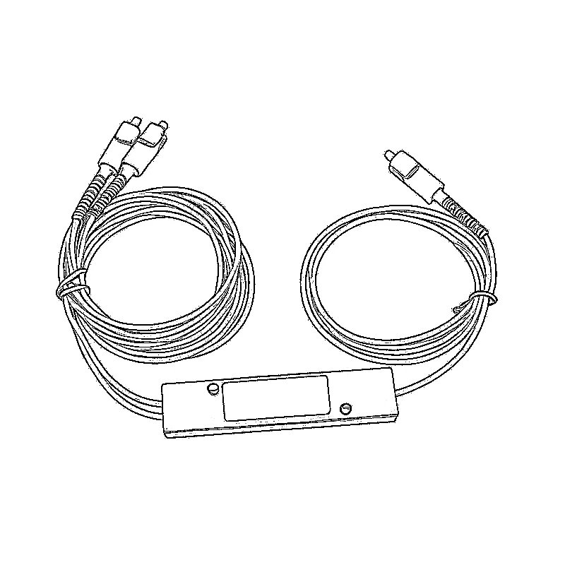

Yes—many passive couplers allow light to travel both ways, so using a fiber splitter in reverse can guide optical signals from branch ports toward a common port. That is what a pon splitter does for upstream traffic.
But there is an important limit: combining light is not the same as combining independent data links. A passive splitter has no packet switching, buffering, wavelength selection or transmission scheduling. The complete system must prevent signals from interfering with one another.
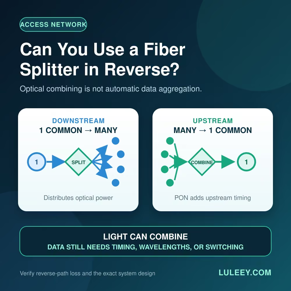
Can You Use a Fiber Splitter in Reverse? The Short Answer
Use this decision table before connecting anything:
| Use case | Does light reach the common port? | Does the network work? |
|---|---|---|
| Registered ONUs transmitting upstream on a designed PON | Yes | Yes, because the PON system coordinates upstream transmissions |
| One test source connected from a branch port to the common port | Usually, within the component’s wavelength and loss specifications | Possibly; verify reverse-path loss and receiver power |
| Two independent same-wavelength Ethernet transmitters | Optical energy may reach the common port | Not as a normal combined Ethernet link; the splitter provides no traffic coordination |
| Several planned wavelength channels | A power splitter may pass the light, but with unnecessary splitting loss and no wavelength separation | Use a wavelength-specific WDM mux/demux design |
| Two feeder ports intended for protection | Depends on the exact 2×N component | Redundancy and switching behavior must be provided by the system, not assumed from the splitter |
The practical rule is simple: a splitter can combine optical paths, but it cannot decide how unrelated transmitters share the path.
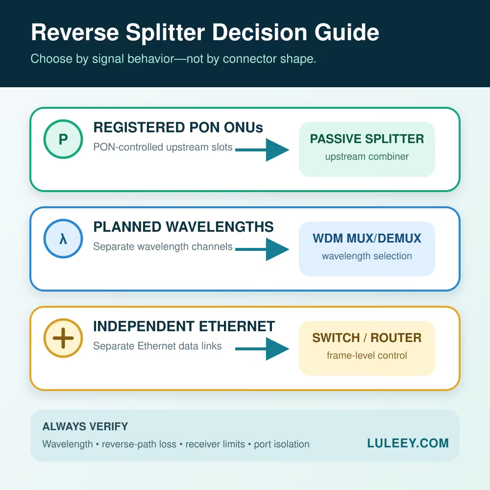
Why a Passive Fiber Splitter Can Work Both Ways
The Fiber Optic Association describes optical couplers as passive devices that can split or combine signals. It also notes that these devices are generally bidirectional: a 1×N device distributes light from the common port in one direction and combines light toward that port in the other direction.thefoa.org
The labels “input” and “output” often describe the normal installation direction. They do not necessarily mean that the component behaves like an optical diode.
However, “generally bidirectional” is not permission to assume identical performance in both directions. FOA notes that some fused couplers can have similar loss either way, while integrated optical splitters may have different directional loss. Wavelength response, port uniformity, crosstalk, connector loss and the exact internal design also matter.
Use the reverse-direction specification when the manufacturer provides one. If it is not documented, measure the actual branch-to-common path before relying on it.
Why Reverse Operation Works in PON
A passive optical network is designed around this two-way behavior:
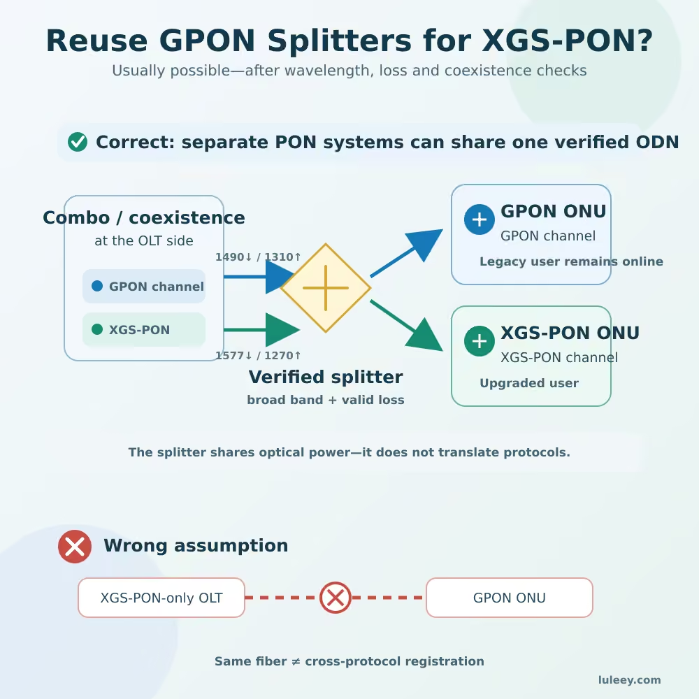
- Downstream: the OLT sends one optical stream into the common port, and the splitter distributes it toward multiple ONUs or ONTs.
- Upstream: the ONUs send from the branch ports, and the same splitter guides their light toward the shared OLT port.
The splitter does not prevent upstream collisions. The PON protocol and OLT control when each registered ONU may transmit. Common PON systems use time-division multiple access for upstream traffic, so the OLT receives separated bursts rather than several uncontrolled transmitters talking at once.Cisco
PON also uses a defined wavelength plan to separate upstream and downstream traffic on the same feeder fiber. These controls come from the active PON equipment and protocol—not from the passive splitter.
This is why adding another splitter or ONU does not automatically create another working service. Optical budget, ONU compatibility, registration, authentication and OLT provisioning still apply. LuLeey’s guide on adding a fiber splitter to an FTTH line explains those additional checks.
Why a Reverse Splitter Does Not Merge Ordinary Ethernet Links
Imagine connecting the transmit outputs of two ordinary same-wavelength Ethernet SFP links to the branch ports of a 1×2 splitter, then connecting the common port to one receiver.
The splitter has no way to:
- Read Ethernet frames
- Buffer one transmitter while the other is active
- Assign transmission time slots
- Separate two overlapping signals at the same wavelength
- Negotiate link speed or duplex mode
- Forward traffic to the correct destination
If both transmitters operate at once, the receiver can see overlapping optical signals that it was not designed to separate. A specially designed shared-medium optical system can coordinate multiple transmitters, but the splitter alone does not create that system.
To combine ordinary Ethernet traffic, use an Ethernet switch or router. If the requirement is to place several defined wavelengths on one fiber, use a correctly designed WDM mux/demux system with matched transceivers and a verified wavelength plan.
Fiber Splitter vs WDM Mux vs Ethernet Switch
| Device | What it combines | What it does not do | Typical use |
|---|---|---|---|
| Passive power splitter/coupler | Optical power between common and branch ports | No frame processing, scheduling or wavelength selection | PON distribution, monitoring and engineered optical coupling |
| WDM mux/demux | Separate, defined wavelength channels | Does not switch Ethernet frames or correct an invalid wavelength plan | Several optical channels sharing one fiber |
| Optical switch | Selects one optical path under control | Does not merge simultaneous Ethernet traffic | Protection, path selection or test automation |
| Ethernet switch/router | Frames or packets from separate links | Does not pass raw optical signals without suitable interfaces | Combining and forwarding independent data connections |
Do not choose among these devices by connector type alone. Two products can both use SC/APC or LC/UPC while performing completely different jobs.
Reverse-Direction Loss Still Counts
Running a splitter backward does not recover the power lost by the split ratio.
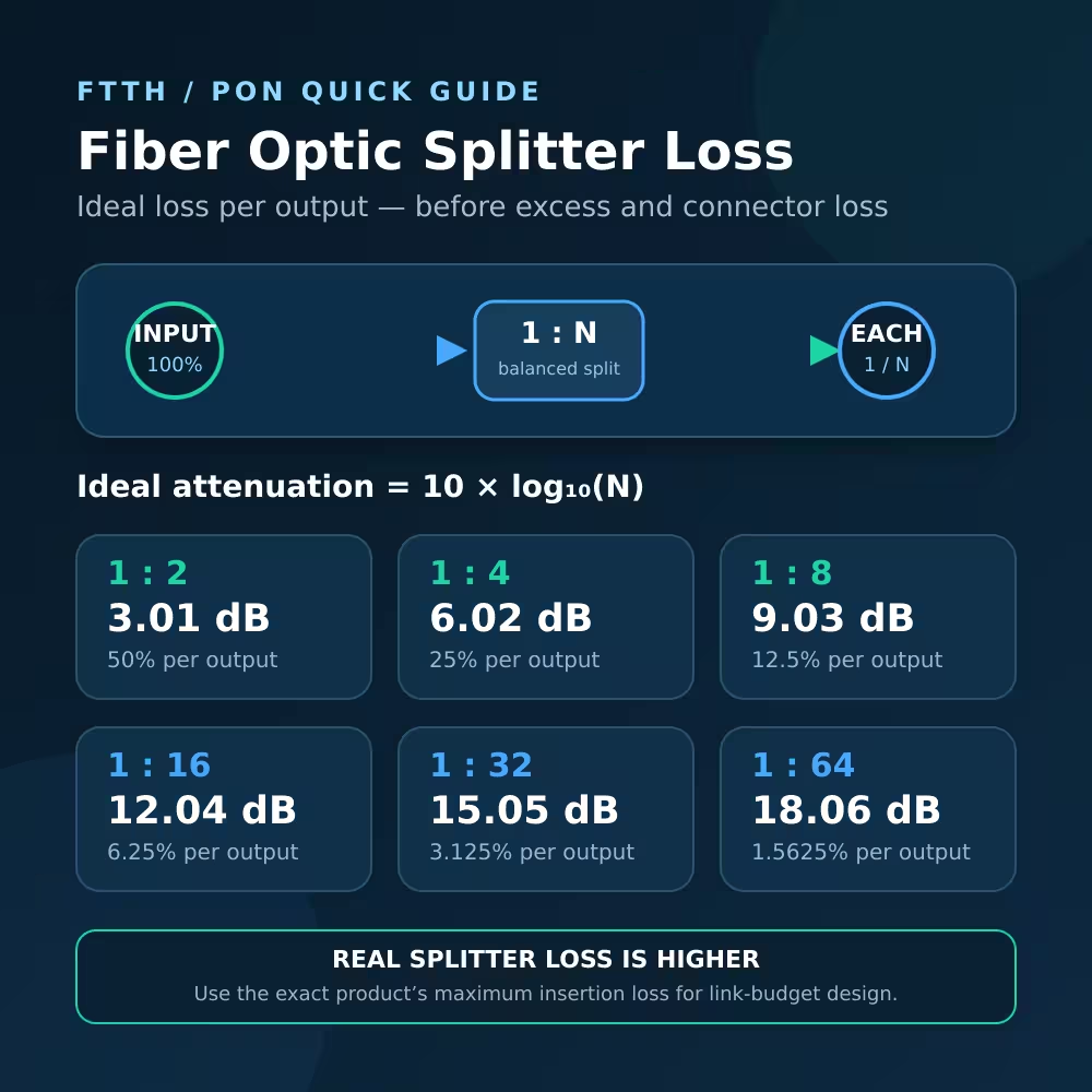
For a balanced 1×N device, the ideal division term is:
Ideal splitting loss = 10 × log10(N)
That is about 3.01 dB for 1×2, 6.02 dB for 1×4 and 9.03 dB for 1×8 before excess loss. These values are useful starting points, not finished product specifications.
For reverse operation:
- Use the documented loss from each branch to the common port.
- Check the operating wavelength range.
- Include connector, adapter, splice and fiber loss.
- Check both receiver sensitivity and overload limits.
- Confirm whether branch-to-branch isolation or crosstalk matters.
- Do not add dBm values arithmetically when several sources are active.
LuLeey’s fiber optic splitter loss guide explains the ideal loss formula and why an actual splitter’s maximum insertion loss is higher.
A Practical Example
Consider a 1×4 splitter in a GPON optical distribution network.
In the downstream direction, the OLT signal enters the common port and is divided among four branches. In the upstream direction, each registered ONU transmits during its assigned opportunity, and its burst travels from a branch port through the splitter to the common OLT port.
Now replace those ONUs with four unrelated point-to-point Ethernet transmitters. The optical component may still guide energy toward the common port, but the PON scheduling mechanism is gone. The transmitters do not automatically take turns, and one ordinary receiver cannot separate overlapping same-wavelength streams.
The glass did not change. The system behavior did.
How to Evaluate a Reverse-Splitter Idea
1. Define the required result
Are you combining a coordinated PON upstream, planned wavelengths, a monitoring signal, one selected path, or independent Ethernet traffic? These are different engineering problems.
2. Identify the exact passive component
Record PLC or FBT construction, 1×N or 2×N port arrangement, balanced or unequal ratio, connector type and polish, operating wavelengths and package type.
3. Obtain reverse-path data
Look for branch-to-common insertion loss, uniformity, return loss, directivity or crosstalk where relevant. Do not claim reverse performance from the front label alone.
4. Check the active equipment
Confirm the transmitter wavelengths and power, receiver limits, protocol, timing method and whether the equipment was designed for a shared optical path.
5. Test one path at a time
Measure the loss from each intended branch to the common port at the working wavelength. Then perform a controlled functional test without exposing live receivers to unknown combined power.
Common Mistakes
- Assuming “bidirectional” means any data sources can share the fiber
- Treating a power splitter as a wavelength-selective mux
- Ignoring reverse-direction insertion loss
- Connecting several live transmitters before checking receiver overload
- Assuming a 2×N splitter provides automatic OLT protection
- Choosing by SC or LC connector shape instead of signal behavior
- Forgetting that a new splitter stage consumes optical budget
Practical Next Step
Write the intended signals in a four-column worksheet: source, wavelength, transmit timing and destination receiver. If the sources are registered PON ONUs under one OLT, a passive splitter is part of the normal upstream design. If the signals use distinct planned wavelengths, design a WDM link. If they are independent Ethernet connections, use a switch or router.
After the architecture is clear, calculate the reverse path with the exact component data. LuLeey’s optical splitters and splitter boxes category can be used to compare available ratios, connector polishes and package types, but the current category listing alone does not establish reverse-direction loss for every model.







 SFP/SFP+ (1G/2.5G/5G/10G)
 SFP-T (1G/2.5G/10G)
 AOC Cable 10G/25G/40G/100G
 DAC Cable 10G/25G/40G/100G
 QSFP28 QSFP+ SFP28 100G/40G/25G
 Copper to Fiber Media Converters
 Fiber Media Converter PCBA Board
 OEO Fiber Media Converters
 Serial to Fiber Media Converters
 Video to Fiber Media Converters
 1000M GPON/EPON ONU
 10G EPON ONU/XG-PON/XGS-PON
 2.5G GPON/XPON STICK SFP ONU
 POE GPON/EPON ONU
 Wireless GPON/EPON ONT
 EPON OLT
 GPON OLT
 SFP PON Module
 Industrial Switches
 Managed Switches
 POE Switches
 Unmanaged Switches
 MTP/MPO Fiber Cables
 Fiber Optic Cassettes
 Fiber Optic Loopback
 Optic Cables and Fiber Pigtails
 Optical Splitters and Splitter Box
 Fiber Flange Connectors
 Optical Adapters
 Optical Attenuator
 Quick Connector and Connector Panel
 CATV Amplifier
 CATV Optical Receiver
 Visual Fault Locator
 OTDR
 Optical Power Meter
 Fiber Optic Identifier
 Fiber Optic Cleaners
 Fiber Cleavers & Fiber Strippers
 Copper Tools