Customs duties are the responsibility of customers, but standard logistics support DDP to most countries, duty-free such as US, DE, UK, CA, FR, IT, PL, AT, JP…





















































You can connect a GPON ONU directly to an OLT in a controlled one-ONU lab, but a bare short patch cord may deliver too much optical power. Omitting the splitter does not remove the need for a valid optical loss budget. In many test setups, a correctly selected fixed or variable attenuator is required to keep both receivers below their overload limits.
You also need a real GPON OLT—not a normal Ethernet switch with a similar-looking SFP cage. The OLT must generate GPON downstream frames, discover and range the ONU, assign upstream transmission opportunities, manage the ONU and provision services.
The safe answer therefore has three parts:
- A splitter is not inherently required for a one-ONU protocol test.
- Controlled optical attenuation may still be required in both directions.
- Optical link-up is only the first layer; ONU activation and service configuration must also be completed.
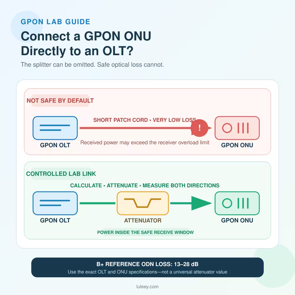
Connect a GPON ONU Directly to an OLT: Quick Answer
| Question | Short answer | What must be checked |
|---|---|---|
| Can one ONU connect without a splitter? | Yes, in an engineered lab | Exact GPON optics, total loss, connector polish and authorization |
| Can I use only a short patch cord? | Not safely by default | Transmit power and Receiver Overload in both directions |
| Is a fixed attenuator always needed? | Often, but the value is not universal | Measured power, optical class, path loss and margin |
| Can an Ethernet SFP act as a GPON OLT? | No | A real OLT must implement GPON PMD, TC, ranging, burst reception and management |
| Will a detected ONU automatically pass traffic? | No | Discovery, activation, OMCI/profile, VLAN and WAN/service settings |
| Will direct connection provide 2.5 Gbit/s to a 1GE ONU? | No | GPON line rate, ONU LAN interface and test endpoints all limit throughput |
A green PON LED is not proof that optical power is safe or that Internet traffic is configured correctly.
Does GPON Need a Splitter to Work?
GPON was designed for a point-to-multipoint optical distribution network. One OLT port can serve multiple ONUs through a passive splitter. Downstream traffic is sent from the OLT toward the ONUs, while the OLT schedules upstream bursts so that subscriber transmissions do not collide.
The splitter performs an optical function: it divides downstream power and combines upstream light. It does not generate GPON frames, assign ONU IDs, perform ranging or create VLANs.
With only one ONU in a private test setup, a direct optical path can still carry the GPON protocol. The OLT continues to:
- Send the downstream GPON signal
- Discover the ONU identity
- Assign an ONU-ID
- Measure and compensate for propagation delay through ranging
- Grant upstream transmission time
- Manage the ONU through the supported control method
- Map subscriber traffic to service profiles and VLANs
ITU‑T G.984.3 defines the GPON transmission-convergence layer. Its activation and ranging functions remain necessary even when the physical path contains one ONU and no splitter.
Removing the splitter changes the optical loss; it does not turn GPON into point-to-point Ethernet.
Why a Direct GPON Link Can Overload the Receivers
Optical receivers have two important limits:
- Sensitivity: the weakest received power at which specified performance is expected
- Overload: the strongest received power at which specified performance is expected
Too little power can cause loss of signal and errors. Too much power can also cause errors, unstable behavior or receiver saturation. A link must stay between the two limits with suitable engineering margin.
For the common 2.488 Gbit/s downstream and 1.244 Gbit/s upstream GPON B+ application, ITU‑T G.984.2 lists:
| B+ parameter | OLT side | ONU side |
|---|---|---|
| Mean launched power | +1.5 to +5 dBm | +0.5 to +5 dBm |
| Minimum receiver sensitivity | −28 dBm | −27 dBm |
| Minimum receiver overload | −8 dBm | −8 dBm |
The same annex gives a B+ ODN loss range of 13 to 28 dB at both 1490 nm downstream and 1310 nm upstream.
A short, clean patch cord can have far less than 13 dB of loss. That is why direct physical connection is not automatically a valid B+ optical setup.
These B+ numbers are not universal values for every OLT or ONU. Other optical classes and vendor implementations can have different launch-power, sensitivity, overload and minimum-loss specifications. Always use the exact data for both devices.
A Simple Downstream Power Example
Suppose the OLT’s actual downstream transmit power is measured as +3 dBm, and the patch cord, adapters and test meter together add 1 dB of loss.
Without an added attenuator:
ONU received power = +3 dBm − 1 dB = +2 dBm
The B+ ONU overload value in the table above is −8 dBm. In this example, +2 dBm is 10 dB stronger than −8 dBm, so the direct path is outside that standardized B+ receiver range.
If the engineer adds a verified 15 dB attenuator:
ONU received power = +3 dBm − 1 dB − 15 dB = −13 dBm
That illustrative result is below the B+ overload level and above the B+ sensitivity level. It is not a recommendation to use 15 dB in every setup.
The correct attenuation depends on:
- Actual OLT transmit power, not only a nominal label
- Actual ONU overload and sensitivity limits
- ONU upstream transmit power and OLT burst-receiver limits
- Patch cord, adapter, meter and attenuator loss at the relevant wavelengths
- Measurement uncertainty and required margin
- The exact optical class and environmental conditions
Do the upstream calculation separately. One passive attenuator in a single-fiber GPON path normally affects both 1490 nm downstream and 1310 nm upstream, but its actual attenuation must be known at both wavelengths.
How to Calculate the Required Attenuation
For either direction:
Received power = Transmit power − total path loss
To stay below the receiver overload limit:
Minimum total path loss ≥ maximum transmit power − overload limit
To stay above the receiver sensitivity limit:
Maximum total path loss ≤ minimum transmit power − sensitivity limit
Use worst-case values when designing a repeatable setup. The strongest possible transmitter combined with the least path loss is the overload case. The weakest possible transmitter combined with the greatest path loss is the sensitivity case.
Then add the losses of:
- The selected attenuator at 1310 nm and 1490 nm
- Patch cords and adapters
- An in-line PON power meter, if used
- Any coupler, filter or monitoring tap
- Connector repeatability and reasonable test margin
Do not choose an attenuator from the splitter ratio you removed. Measure or calculate the complete test path against the exact devices.
Why a Normal Ethernet SFP Cannot Replace a GPON OLT
A standard Ethernet transceiver and a GPON OLT optical interface can share a pluggable form factor, but their functions are different.
An Ethernet optical link normally expects another compatible point-to-point Ethernet PHY. A GPON OLT must provide:
- GPON downstream framing at the correct wavelength and line rate
- ONU discovery and identity handling
- Ranging and equalization-delay control
- Upstream bandwidth maps and time-slot grants
- Burst-mode upstream reception from ONUs
- Dynamic bandwidth allocation
- PLOAM and OMCI-related management functions
- Subscriber traffic mapping and operational alarms
A generic Ethernet SFP does not acquire these functions because its wavelength, connector or nominal bit rate looks similar. Likewise, an OLT PON module requires a host platform and software that implement the expected PON MAC/TC and management interfaces. The pluggable module alone is not necessarily a complete standalone OLT.
Use an actual GPON OLT or a documented OLT host-and-PON-module combination.
What You Need for a One-ONU GPON Lab
A basic authorized setup normally includes:
- A GPON OLT with its supported PON optical interface
- A compatible GPON ONU or ONT
- Single-mode patch cords with matching connector family and polish
- A verified fixed or variable Optical Attenuator when required
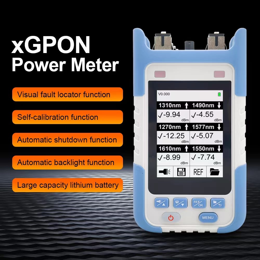
- A suitable PON power meter or approved optical measurement arrangement
- Management access to the OLT
- Ethernet test endpoints for service and throughput checks
- Device documentation, optical specifications and a connection record
The University of New Hampshire InterOperability Laboratory’s PON Integrator Test Plan illustrates an OLT–ODN–ONU test arrangement using short fibers, a splitter and additional attenuation. It also uses an in-line optical power meter in a one-ONU test. This reinforces the lab principle: short test fibers do not remove the need to control and measure optical power.
That published setup is a specific interoperability method, not a universal instruction to copy its 1:8 splitter or 10 dB attenuator into every direct-link experiment.

An Eight-Step Direct-Connection Workflow
Step 1: Confirm that both devices are GPON
Record the OLT model, PON port or module, ONU model, hardware revision and firmware. Confirm that the ONU supports GPON—not only EPON, XG-PON or XGS-PON.
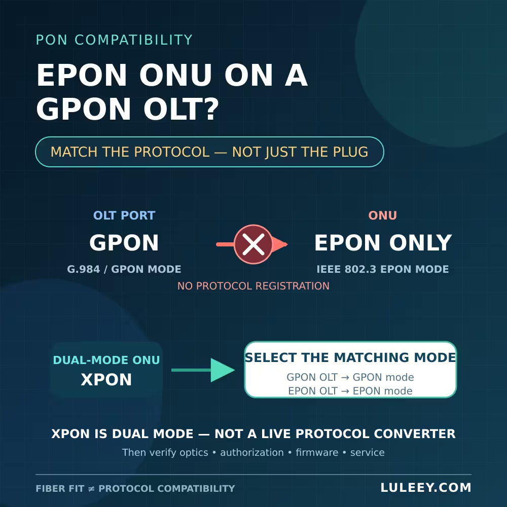
A product called “XPON” often supports GPON and EPON dual mode. That label does not prove XGS-PON support.
Step 2: Collect the optical specifications
For both directions, record:
- Wavelength range
- Minimum and maximum transmit power
- Receiver sensitivity
- Receiver overload
- Optical path class
- Minimum and maximum required ODN loss
- Connector type and APC/UPC polish
If the product page does not publish these values, obtain the exact datasheet or ask the vendor. Do not substitute a generic B+ table for an unverified device.
Step 3: Calculate the safe loss window
Calculate downstream and upstream independently using the strongest and weakest transmit conditions. Include every passive element and the measurement uncertainty.
Choose a starting attenuation that keeps the predicted received power safely below overload while remaining above sensitivity. A variable attenuator can simplify controlled testing, but only if its wavelength range, accuracy, connector interfaces and power handling are suitable.
Step 4: Match and inspect the optical interfaces
Use single-mode fiber and match SC/APC to SC/APC or SC/UPC to SC/UPC. Do not directly mate APC and UPC connectors. Inspect and clean accessible end faces using approved tools.
Never look into the OLT or ONU fiber port. Treat it as active even when the management interface reports the port down.
Step 5: Install attenuation before enabling the link
Follow the equipment’s approved shutdown and connection procedure. Put the calculated attenuator and any measurement device into the path before enabling the PON transmitter.
Record the exact attenuator value and where it is installed. A plug-in attenuator placed at a receiver can also help protect that receiver during reconnection, but its loss still affects the complete bidirectional path.
Step 6: Measure and verify both directions
Confirm the downstream level at the ONU and the upstream burst level at the OLT using supported equipment and methods. A basic continuous-wave optical power meter may not capture an ONU’s burst-mode upstream transmission correctly.
OLT and ONU diagnostic readings are useful cross-checks, but their availability, calibration and update behavior vary. Do not treat a displayed value as a substitute for a calibrated acceptance method.
Step 7: Discover, authorize and activate the ONU
Use the OLT’s authorized workflow to discover the ONU, assign or approve its identity, complete ranging and bring it into the operational state. Configure only unique, authorized serial-number, registration-ID, password or LOID information.
Do not clone a subscriber identity. Duplicate identifiers can cause conflicts and may violate the network owner’s policy.
Step 8: Provision and validate the service
Apply the correct ONU profile, T-CONT/GEM mapping, VLAN behavior and LAN-side service settings for the lab. Then verify:
- Stable operational state
- Received optical power in both directions
- No optical or burst-reception alarms
- Ethernet link speed on the ONU LAN port
- Bidirectional traffic and packet loss
- VLAN, DHCP or PPPoE behavior where relevant
- Stability after reboot and over time
Change one variable at a time if the test fails.
If the ONU Does Not Register
| Observation | More likely cause | First useful check |
|---|---|---|
| No optical signal at the ONU | Wrong port, cable, connector, disabled OLT laser or excessive loss | Verify topology, connector polish and downstream power |
| Very high downstream power | Too little attenuation | Disable safely and recalculate before reconnecting |
| ONU is discovered but not authorized | Identity or OLT policy | Check the approved serial/registration method and whitelist |
| ONU stops during ranging | Optical level, burst reception, compatibility or configuration | Check both directions, alarms and exact ONU profile |
| ONU reaches operational state but no traffic passes | Service profile, GEM/T-CONT, VLAN or LAN configuration | Inspect provisioning rather than adding optical power |
| Traffic works but throughput is lower than expected | 1GE LAN port, service profile, test endpoint or shared resources | Confirm every interface rate and run a controlled local test |
Do not increase optical power to solve a provisioning problem. More light does not create the missing ONU profile or VLAN.
Common Direct-Link Mistakes
Assuming the splitter is required for ranging
Ranging is performed by the OLT and ONU protocol. A splitter is part of the normal optical tree, but it is not the device that calculates equalization delay.
Assuming no splitter means no Optical Budget
The short link still has a minimum-loss problem. Receiver overload is the main risk that users miss.
Selecting one universal attenuator value
Ten or fifteen decibels may be reasonable in a specific lab, but neither is universally correct. Calculate both directions with the actual optical class and verify by measurement.
Using a normal Ethernet transceiver as the OLT
Mechanical fit and similar data rates do not provide GPON framing, ranging, upstream grants or burst-mode reception.
Mixing APC and UPC
The connector family may look compatible, but the end-face geometries are different. Directly mating them can add loss, reflectance and physical damage.
Treating O5 or “Online” as a complete service test
An operational ONU may still have no working Ethernet service because GEM mapping, VLANs, DHCP, PPPoE or access policy is incomplete.
Applying the Method to LuLeey Equipment
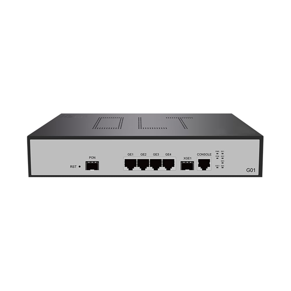
LuLeey’s LL‑GPOLT‑G01 1‑PON GPON OLT page lists one GPON port, four 10/100/1000BASE‑T uplinks, one SFP+ uplink, ONU discovery/authorization, DBA, VLAN functions and CLI/WEB/SNMP/NMS management.
LuLeey’s LL‑XP1GE 1GE XPON ONU page lists GPON/EPON dual-mode operation, one 10/100/1000Mbps RJ45 port, SC/APC or SC/UPC optical versions, automatic discovery and registration, OMCI/OAM, DBA and VLAN support. Its 1GE LAN port also means end-to-end user traffic cannot exceed that Ethernet interface’s practical capacity.
The verified LuLeey fixed optical attenuator page currently offers FC/APC, FC/UPC, SC/APC and SC/UPC fixed male-to-female variants and selectable values from 0 to 30 dB. The page’s specification lists single-mode working wavelengths of 1310 and 1550 nm.
Because GPON downstream commonly uses the 1480–1500 nm band, confirm the exact ordered attenuator’s calibrated attenuation and tolerance at 1490 nm as well as 1310 nm before approving it for this lab. Do not infer complete GPON wavelength performance from the connector name or attenuation label alone.
Before ordering a complete setup, provide LuLeey with:
- Exact OLT and PON optical-interface option
- ONU model, hardware and firmware
- Optical class and transmit/receive limits
- Connector family and APC/UPC polish
- Calculated loss window in both directions
- Required fixed or variable attenuation range
- Measurement method and target wavelengths
- OLT authentication and ONU profile requirements
- Expected LAN rate and traffic test method
Final Answer
You can connect one GPON ONU directly to a real GPON OLT in a controlled lab without using a splitter. The splitter is not required to create GPON framing, discovery, ranging or upstream scheduling.
However, a short patch cord may provide far less loss than the optics were designed to see. For GPON B+, ITU‑T G.984.2 gives a 13–28 dB ODN loss range, so direct connection can exceed the receiver overload limit unless suitable attenuation is added.
Use this order:
- Verify the exact GPON OLT, ONU and optical class.
- Record transmit, sensitivity and overload specifications.
- Calculate the safe downstream and upstream loss windows.
- Match fiber and APC/UPC interfaces.
- Install verified attenuation before enabling the link.
- Measure received power using a suitable PON method.
- Discover, authorize and range the ONU.
- Configure the service and validate traffic.
Share the exact optics, connector polish, measured power and desired lab topology with LuLeey before selecting an attenuator. Those details determine a safe value more reliably than copying a splitter loss or another user’s setup.


 SFP/SFP+ (1G/2.5G/5G/10G)
 SFP-T (1G/2.5G/10G)
 AOC Cable 10G/25G/40G/100G
 DAC Cable 10G/25G/40G/100G
 QSFP28 QSFP+ SFP28 100G/40G/25G
 Copper to Fiber Media Converters
 Fiber Media Converter PCBA Board
 OEO Fiber Media Converters
 Serial to Fiber Media Converters
 Video to Fiber Media Converters
 1000M GPON/EPON ONU
 10G EPON ONU/XG-PON/XGS-PON
 2.5G GPON/XPON STICK SFP ONU
 POE GPON/EPON ONU
 Wireless GPON/EPON ONT
 EPON OLT
 GPON OLT
 SFP PON Module
 Industrial Switches
 Managed Switches
 POE Switches
 Unmanaged Switches
 MTP/MPO Fiber Cables
 Fiber Optic Cassettes
 Fiber Optic Loopback
 Optic Cables and Fiber Pigtails
 Optical Splitters and Splitter Box
 Fiber Flange Connectors
 Optical Adapters
 Optical Attenuator
 Quick Connector and Connector Panel
 CATV Amplifier
 CATV Optical Receiver
 Visual Fault Locator
 OTDR
OTDR Optical Power Meter
 Fiber Optic Identifier
 Fiber Optic Cleaners
 Fiber Cleavers & Fiber Strippers
 Copper Tools


