Customs duties are the responsibility of customers, but standard logistics support DDP to most countries, duty-free such as US, DE, UK, CA, FR, IT, PL, AT, JP…





















































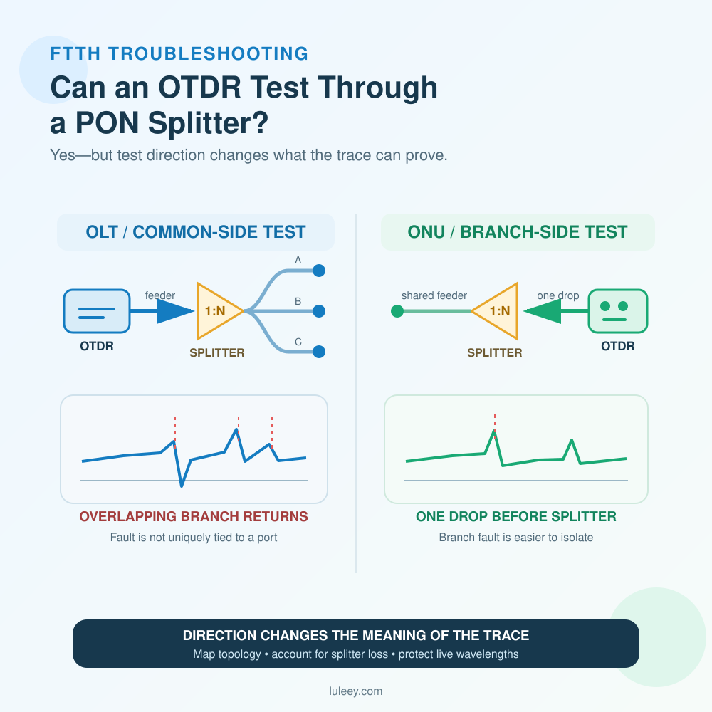
An OTDR can test through a PON Splitter, but the result depends heavily on the test direction, splitter loss, branch layout, wavelength and instrument capability. From the OLT or common side, a conventional OTDR receives backscatter from all output branches at the same time. It may show the splitter and some branch ends, but it usually cannot tell you which branch contains a particular fault.
Testing from the affected ONU side changes the topology seen by the instrument. The OTDR first measures one subscriber drop, then crosses the splitter toward the shared feeder. This direction is normally much more useful for locating a fault on that specific drop.
Do not connect a general-purpose OTDR to an unknown Live PON. An in-service test requires a wavelength and filtering method designed for the actual PON wavelength plan, plus the network owner’s approved procedure.
OTDR Test Through a PON Splitter: Quick Answer
| Test situation | What the trace can usually tell you | Main limitation or next step |
|---|---|---|
| OTDR at the OLT/common side | Feeder events, splitter location, composite branch response and some reflective branch ends | Post-split backscatter overlaps; one fault may not be attributable to one output |
| OTDR at one ONU/drop side | Events on that individual drop before the splitter and the shared path beyond it | Access and live-network protection are still required |
| Test stops at the splitter | Dynamic range, pulse, range, connection loss or a real break may be limiting the trace | Check loss budget, cleanliness and settings before blaming the splitter |
| Several end reflections appear | Different branch lengths may be visible | An end distance alone does not certify every event on that branch |
| Live PON needs fault location | Possible only with a suitable filtered in-service method | Confirm wavelengths, isolation, power handling and operator procedure |
| Need actual GPON/XGS-PON signal levels | OTDR is not the primary tool | Use a wavelength-selective PON power meter that supports the active system |
An OTDR Trace is evidence, not a complete map. Compare it with the as-built topology, known branch lengths and a healthy baseline trace.
Why a PON Splitter Changes the OTDR Trace
An OTDR launches an optical pulse and measures Rayleigh backscatter and reflections returning to the same port. It estimates distance from the round-trip time and presents returned power as a trace.
A passive splitter creates two separate challenges.
First, it adds substantial loss. Light must pass through the splitter on the outward trip, and backscattered light from fiber beyond the splitter must pass through it again on the return trip. The post-split signal reaching the OTDR is therefore much weaker than the signal from the feeder fiber.
Second, the common-side test changes from one fiber path to many parallel paths. All branches receive the test pulse, and their backscatter returns to the same common port. Events occurring at similar distances overlap on one horizontal distance scale.
The result is a composite trace. A peak at 2.4 km after the test port might be the open end of one branch, a connector on another branch or several events at nearly the same distance. A conventional OTDR has no splitter-port identifier embedded in the backscatter.
The Fiber Optic Association’s FTTH PON testing guide illustrates the different downstream and upstream traces and explains why measurement from the opposite direction is required when a branch problem cannot be isolated from the common side.
Testing from the OLT Side vs the ONU Side
| Question | OLT/common-side test | ONU/branch-side test |
|---|---|---|
| Fiber before the splitter | One feeder path, normally straightforward | Seen after crossing the splitter |
| Fiber after the splitter | Multiple branches superimposed | One selected subscriber drop before the splitter |
| Best use | Feeder fault, splitter location, broad comparison with baseline | Fault location on the selected drop |
| Splitter effect | Large loss followed by composite backscatter | Large loss near the transition to the shared feeder |
| Main ambiguity | Which output branch produced an event | Shared feeder events after the splitter may still need topology records |
| Access requirement | Central office or distribution point | Customer or terminal access to the affected branch |
What an OLT-side trace can do
Testing from the common side can be valuable for:
- Confirming continuity to the splitter
- Locating a feeder break before the splitter
- Detecting a major change at the splitter location
- Seeing some end reflections when branch lengths differ
- Comparing the current composite trace with a known-good baseline
- Identifying that a group of subscribers may share one upstream fault
It should not be treated as a one-shot certification of every branch. A healthy branch can mask the reduced backscatter of a broken branch, and two events at the same distance cannot be separated by port number.
ITU-T L.313, originally published as L.66, states that a conventional central-office OTDR cannot pinpoint faults in the branched region between a splitter and multiple ONTs because the Rayleigh backscatter from the branches is accumulated and cannot be separated. The recommendation is available from the ITU-T L.313 record.
Why ONU-side testing is different
When the OTDR is connected to one subscriber branch, only that drop fiber lies between the instrument and the splitter. A bend, splice, connector or break on that drop can therefore appear before the large splitter event without being mixed with the other outputs.
This direction is often the simplest way to answer: “Where is the fault on this customer’s drop?” It does not remove the splitter loss or the need for a suitable launch cable. It also does not authorize disconnecting a subscriber or injecting test light into an active network.
If several subscribers fail at once, begin with topology and service data. Their common point may be the feeder, first-stage splitter, enclosure, OLT port or a power/provisioning issue rather than several separate drop breaks.
How Much Loss Does the Splitter Add to the Trace?
For an ideal balanced 1×N splitter, the one-way division loss is:
Ideal splitter loss = 10 × log10(N)
An ideal 1×32 split therefore has:
10 × log10(32) ≈ 15.05 dB
A real splitter has excess loss and output variation. LuLeey’s verified 1×32 SC/UPC PLC splitter lists maximum insertion loss of 17.3 dB, loss uniformity of 1.2 dB or less and an operating wavelength range of 1260–1650 nm.
That 17.3 dB is a one-way component specification. The OTDR’s returned signal from beyond the splitter experiences splitter loss on the outbound and return paths. However, do not simply label the displayed splitter event as 34.6 dB. OTDR event algorithms, composite backscatter from many branches, reflectance, pulse width and analysis markers affect what the trace reports.
Use LuLeey’s fiber optic splitter loss guide when calculating the real one-way network budget. Use the actual OTDR trace and instrument method for fault analysis.
Why More Dynamic Range Is Not the Whole Answer
More usable dynamic range helps the OTDR detect weak backscatter after a high-loss splitter. It does not separate branches that physically return overlapping signals.
Instrument setup also creates a trade-off:
- A shorter pulse improves spatial resolution and helps separate nearby connectors, splices and short drops.
- A longer pulse sends more energy and can improve reach, but it increases dead zones and may merge nearby events.
- More averaging can improve signal-to-noise ratio without the same resolution penalty as a large pulse increase, but the test takes longer.
- A correct distance range must cover the launch cable, route and longest relevant branch.
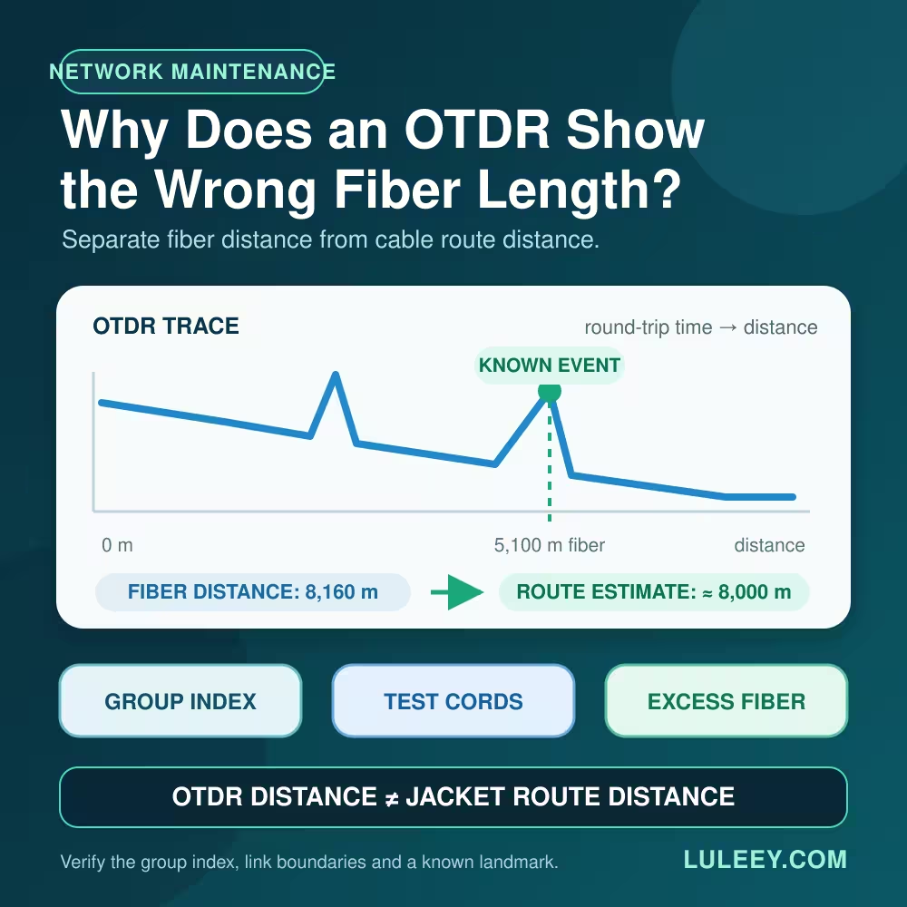
- A correct group index improves distance accuracy but does not identify splitter ports.
Start with the shortest pulse that still reaches the area of interest, then increase averaging. Change one setting at a time and save each trace. There is no universal dynamic-range number that guarantees passage through every 1×32 or 1×64 PON; the complete loss, branch length, reflectance, noise floor and instrument method matter.
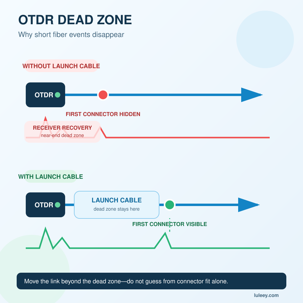
If the first connection is hidden, solve that problem before interpreting the splitter. LuLeey’s guide to OTDR dead zones and launch cables explains why a suitable launch cable creates a stable backscatter baseline before the first network event.
Can You Use an OTDR on a Live PON?
Only use a method explicitly designed and approved for the live system.
A normal 1310 nm or 1550 nm OTDR can overlap operational or overlay wavelengths, interfere with service or be affected by incoming communication light. A powered OLT or ONU can also send light into the OTDR receiver.
ITU-T L.313 defines maintenance-band and filtering considerations for in-service access-network testing. Its fundamental requirements are that test light must not degrade communication signals and that measurement equipment must handle interference from communication light. Filters can be required at both the communication equipment and test instrument.
Filtered OTDRs commonly use an out-of-band maintenance wavelength such as 1625 nm or 1650 nm. That label alone is not proof that an instrument is safe for every live PON. Verify:
- The actual GPON, XG-PON, XGS-PON, EPON or coexistence wavelength plan
- Any RF-video, monitoring or other overlay wavelengths
- Built-in filter passband and rejection/isolation specifications
- Maximum incoming-power tolerance
- OLT, ONU and coexistence-element requirements
- Connector type and polish
- Network-owner procedure and approved connection point
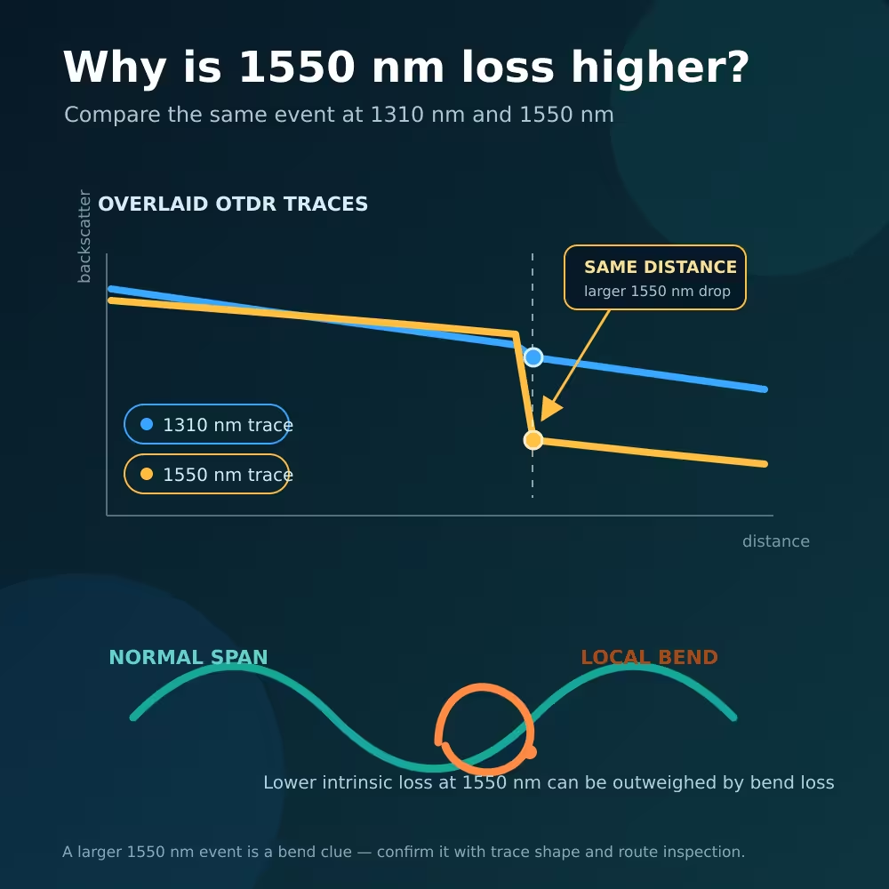
Macrobend response can also differ by wavelength. A bend seen strongly at a maintenance wavelength may have a different loss at the service wavelengths, so correlate the fault with power measurements and the physical route.
Never look into the fiber. Treat every unknown connector as active until it has been checked with the correct procedure and equipment.
What an OTDR Can and Cannot Prove on a PON
| OTDR can help with | OTDR alone cannot prove |
|---|---|
| Distance to a reflective end or break | Which splitter port produced every common-side event |
| Location of feeder events before the splitter | Correct GPON or XGS-PON optical power at the ONU |
| Location of events on one drop when tested from that branch | ONU activation, OMCI, LOID or serial-number authorization |
| Comparison with a stored healthy trace | Correct VLAN, DHCP, PPPoE, Internet, IPTV or voice service |
| Changes in backscatter, loss and reflectance | End-to-end insertion loss under every required acceptance method |
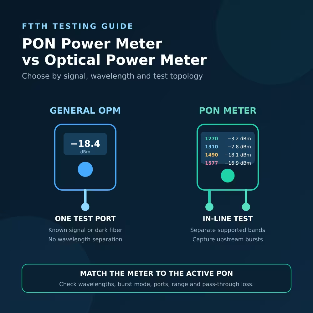
An OTDR is a location and event-analysis tool. A wavelength-selective PON power meter measures active channel levels. OLT and ONU management data confirms activation and service state. A complete diagnosis may require all three.

An Eight-Step PON OTDR Troubleshooting Workflow
Step 1: Define the symptom
Record whether one subscriber, one splitter group or the entire PON port is affected. Confirm whether the physical optical state changed or only an upper-layer service failed.
Step 2: Map the topology
Collect the feeder length, splitter locations and ratios, cascaded stages, output-to-subscriber records and expected branch lengths. Without this map, a composite trace can easily be misread.
Step 3: Decide whether the fiber is live or dark
Verify with the network owner. Do not infer live status from a dark-looking connector or an ONU LED.
Step 4: Select the test direction
Use the OLT/common side for feeder and whole-tree comparison. Use the affected ONU side when the goal is to locate a fault on that specific drop. Test both directions when the evidence and access permit.
Step 5: Confirm the instrument and wavelength
For a live PON, verify the filtered in-service capability against the exact wavelength plan. For a dark network, choose wavelengths and procedures that match the acceptance or maintenance objective.
Step 6: Clean, connect and set the OTDR
Inspect and clean accessible connectors using approved methods. Use a suitable launch cable, set the correct range and group index, begin with a short pulse and add averaging as needed.
Step 7: Compare evidence
Review the trace rather than only the automatic event table. Compare it with the baseline, route map, power readings, alarm times and results from the opposite direction. Do not assign a common-side event to a branch without supporting evidence.
Step 8: Validate the repair
After an authorized repair, repeat the relevant OTDR and power measurements. Then confirm ONU activation, service configuration and traffic. A restored trace does not by itself prove that subscriber services are working.
OTDR or PON Power Meter: Which One Do You Need?
Choose the instrument from the question you need to answer.
| Question | Better starting tool |
|---|---|
| Where is the bend, break, splice or reflective event? | OTDR |
| How much active GPON/XGS-PON power is present at this point? | Wavelength-selective PON power meter |
| Is the ONU registered and provisioned? | OLT/ONU management and service checks |
| Does the completed passive link meet direct insertion-loss requirements? | Approved light source/power meter or OLTS method |
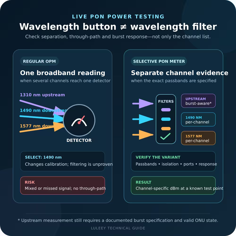
LuLeey’s XPOM002 XGS-PON optical power meter page lists measurement channels for 1310, 1490, 1550, 1270, 1577 and 1610 nm, uncertainty of ±0.5 dB and insertion loss below 1.5 dB. It is listed for live PON measurements.
Those page-level specifications do not establish the correct test method for every network. Before ordering, confirm the exact wavelength option, connector polish, power range, passband, upstream measurement behavior and compatibility with the deployed PON system.
Choosing a LuLeey OTDR Test Setup
LuLeey’s OTDR category includes OTDR instruments and launch cable options. Do not select an OTDR only from its maximum distance or dynamic-range headline.
For a PON troubleshooting request, provide:
- Live or dark test condition
- PON generation and complete wavelength plan
- OLT, ONU and coexistence architecture
- Splitter ratios and number of stages
- Test direction and access point
- Feeder and branch lengths
- Connector family and APC/UPC polish
- Current optical power and alarm state
- Required event resolution and reporting format
- Whether a stored baseline trace exists
LuLeey should confirm the exact OTDR wavelength, filtering, dynamic range, launch cable, connector option and live-network suitability for that topology. A product described only as “PON capable” is not enough for an in-service approval.
Final Answer
An OTDR can often measure beyond a PON splitter when the loss and instrument settings allow it, but the test direction determines what the trace means.
From the OLT/common side, the post-split branches produce a composite return. You can inspect the feeder, splitter and broad changes, but you normally cannot identify every branch fault from one conventional trace. From the affected ONU side, that subscriber drop is isolated before the splitter, making branch-fault location much clearer.
For reliable troubleshooting:
- Map the splitters and branch lengths.
- Identify whether the PON is live.
- Select the test direction for the fault domain.
- Verify the exact wavelength and filtering method.
- Account for the real splitter loss.
- Use a launch cable, short practical pulse and sufficient averaging.
- Compare both directions, baseline traces and optical-power data.
- Validate activation and subscriber service after the repair.
Share the topology, wavelengths, split ratios, route lengths and live-test requirements with LuLeey before choosing an OTDR or PON meter. Those details determine the right setup more reliably than the splitter ratio or OTDR range alone.

 SFP/SFP+ (1G/2.5G/5G/10G)
 SFP-T (1G/2.5G/10G)
 AOC Cable 10G/25G/40G/100G
 DAC Cable 10G/25G/40G/100G
 QSFP28 QSFP+ SFP28 100G/40G/25G
 Copper to Fiber Media Converters
 Fiber Media Converter PCBA Board
 OEO Fiber Media Converters
 Serial to Fiber Media Converters
 Video to Fiber Media Converters
 1000M GPON/EPON ONU
 10G EPON ONU/XG-PON/XGS-PON
 2.5G GPON/XPON STICK SFP ONU
 POE GPON/EPON ONU
 Wireless GPON/EPON ONT
 EPON OLT
 GPON OLT
 SFP PON Module
 Industrial Switches
 Managed Switches
 POE Switches
 Unmanaged Switches
 MTP/MPO Fiber Cables
 Fiber Optic Cassettes
 Fiber Optic Loopback
 Optic Cables and Fiber Pigtails
 Optical Splitters and Splitter Box
 Fiber Flange Connectors
 Optical Adapters
 Optical Attenuator
 Quick Connector and Connector Panel
 CATV Amplifier
 CATV Optical Receiver
 Visual Fault Locator
 OTDR
OTDR Optical Power Meter
 Fiber Optic Identifier
 Fiber Optic Cleaners
 Fiber Cleavers & Fiber Strippers
 Copper Tools


