Customs duties are the responsibility of customers, but standard logistics support DDP to most countries, duty-free such as US, DE, UK, CA, FR, IT, PL, AT, JP…





















































xgs-pon ONU Not Registering? Check O1–O7 States
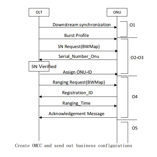
If your XGS-PON ONU is not registering, the most useful first clue is the highest stable O-state it reaches. O1 points to a problem before usable downstream synchronization. O2–O3 narrows the search to discovery and the serial-number phase. O4 means the ONU has progressed to ranging, where upstream burst reception and timing matter. O5 means PON activation is complete, so a no-Internet problem usually belongs to provisioning or the customer-side path instead.
O6 and O7 describe different failures: O6 is recovery from intermittent loss of downstream synchronization, while O7 is an emergency-stop state normally entered after an OLT control action. A state code is a checkpoint, not a complete root-cause diagnosis. Combine it with timestamps, OLT logs, optical data, exact hardware and authorized provisioning records.
Do not start by copying another subscriber’s identifiers, changing attenuation or forcing an unsupported host mode. Record the evidence first and change one approved variable at a time.
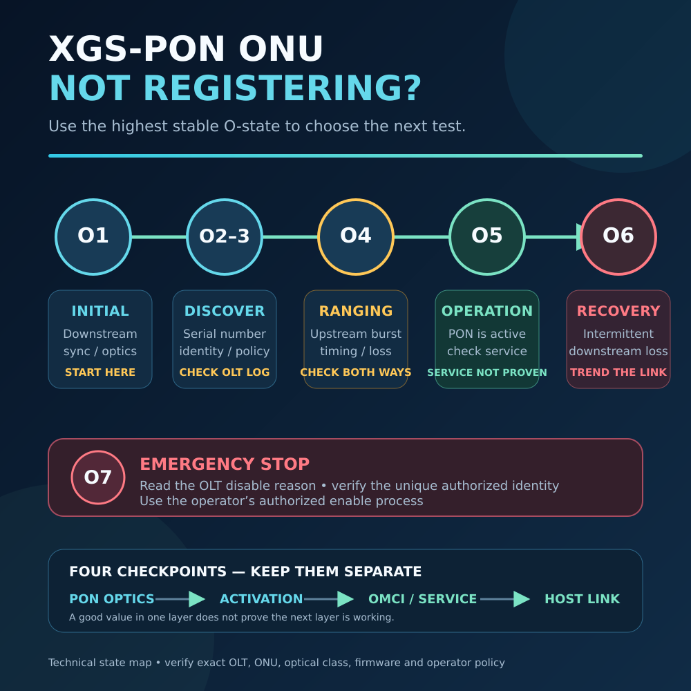
XGS-PON ONU Not Registering: Quick Diagnosis
| Highest stable state | What has already worked | More useful next check |
|---|---|---|
| O1 — Initial | The ONU is powered enough to report state | Correct XGS-PON/XG-PON channel, downstream signal, connector, fiber route and ONU optics |
| O2–O3 — Serial-number/discovery phase | Downstream synchronization and early activation have progressed | OLT discovery records, unique authorized identity, Registration ID policy and interoperability |
| O4 — Ranging | The OLT and ONU have progressed to ranging | Upstream burst power at the OLT, two-way loss window, timing, optical class and firmware |
| O5 — Operation | XGS-PON activation and ranging are complete | OMCI, service profile, T-CONT/XGEM, VLAN, DHCP/PPPoE and host path |
| O6 — Intermittent LODS | The ONU previously operated but lost downstream synchronization | Optical fluctuations, connectors, bends, OLT events, temperature and power |
| O7 — Emergency Stop | The ONU was discovered sufficiently for an OLT control decision | OLT disable reason, identity conflict and authorized re-enable procedure |
| State changes too quickly | The fault is intermittent or the UI samples slowly | Timestamped state history, OLT events and optical/power trends |
Different vendors may combine O2 and O3, expose substates or translate the labels differently. Match the displayed value to the documentation for the exact ONU firmware and OLT release.
What O1 Means: Start Before Authentication
O1 is the initial state. The ONU has not established the downstream synchronization needed to proceed through activation.
Check:
- Whether the OLT port or Combo PON channel supports the exact required PON mode
- Whether the intended OLT transmitter and branch are active
- Connector family and APC/UPC polish
- End-face cleanliness
- Downstream power using an appropriate wavelength-selective method
- The exact OLT/ONU optical-class limits
- Breaks, bends, splitter stages and wavelength-selective passive devices
- ONU power, boot status, firmware and temperature
ITU-T G.9807.1 specifies a nominal 9.95328 Gbit/s XGS-PON line rate in both directions. Its base wavelength plan uses 1575–1580nm downstream and 1260–1280nm upstream, commonly described as 1577 and 1270nm.
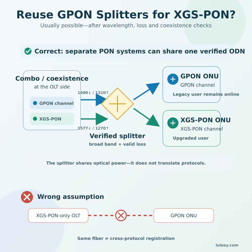
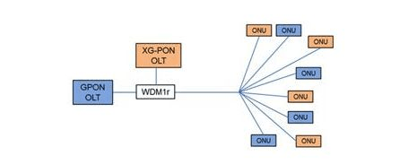
A normal GPON-only port uses different optics and protocol processing. The same fiber or splitter can be part of a coexistence design, but it does not convert one PON generation into another.
LuLeey’s guide to reusing GPON splitters for an XGS-PON upgrade explains this distinction: passive ODN coexistence is possible when the components and budgets are verified, but an XGS-PON ONU still requires an XGS-PON-capable channel.
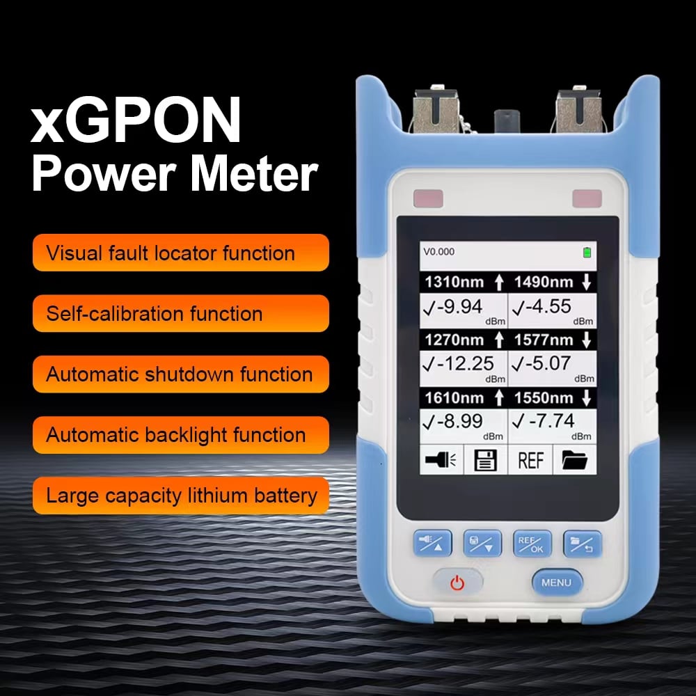
A displayed optical level does not prove that the ONU receives a valid XGS-PON waveform. A broadband meter may also combine multiple active wavelengths unless wavelength-selective filtering is specified.
What O2–O3 Means: Discovery Is Not Complete
XGS-PON implementations commonly present O2 and O3 as a combined serial-number or discovery phase. The ONU has moved beyond its initial state but has not reached ranging.
Collect evidence from both ends:
- Does the OLT discover the reported serial number?
- Does it match the operator’s authorized record?
- Is the same identity active on another ONU or port?
- Does the operator require a Registration ID, password or vendor-specific field?
- Has the ONU entered a quiet or disabled condition?
- Do the OLT card, firmware and ONU firmware support one another?
- Does the state advance briefly and return, or never advance?
Do not reduce O2–O3 to “wrong password.” Discovery timing, OLT policy, duplicate identities, firmware interoperability and an earlier disable action can cause similar symptoms.
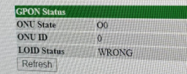
Use only unique, authorized identifiers. Copying another subscriber’s serial number, Registration ID, LOID or MAC address can create conflicts, disrupt service and violate network policy.
What O4 Means: Check Ranging and the Upstream Burst
O4 is the ranging state. The ONU has progressed further than a device that never receives a valid downstream signal or is never discovered.
During ranging, the OLT must receive the ONU’s upstream bursts and establish timing so transmissions from different ONUs arrive in their assigned windows. O4 is therefore a two-direction problem.
Check:
- Upstream received power at the OLT using a supported diagnostic or burst-aware instrument
- Downstream received power at the ONU
- Exact ONU transmitter and receiver specifications
- OLT burst-receiver sensitivity and overload limits
- Splitters, connectors, splices, coexistence elements and total two-way loss
- Route length and configured distance limits
- Ranging, burst-reception and timing alarms
- ONU profiles, firmware and documented interoperability requirements
A normal downstream reading at the ONU does not prove that the OLT receives its 1270nm upstream burst correctly.
Too little loss can also be unsafe in a short laboratory link, while too much loss can prevent field ranging. Do not copy an attenuator value from another setup. Calculate both receive-power windows from the exact equipment specifications and include measurement uncertainty.
What O5 Means: Registration Worked, Service May Not
O5 is the operation state. The ONU has completed XGS-PON activation and can exchange PON-layer traffic with the OLT.
It does not prove that subscriber service is ready. An ONU can remain in O5 while the user has no Internet because of:
- An unsupported or incomplete OMCI profile
- Missing or incorrect T-CONT and XGEM mappings
- VLAN tagging, translation or filtering errors
- DHCP or PPPoE failure
- Service-rate or access-control profiles
- Incorrect bridge or router mode
- A down or incompatible host-side link
- Router, switch, cable or client problems
ITU-T G.988 specifies the ONU management and control interface. Management and service configuration remain distinct from the physical activation state.
Use a layer-by-layer test:
- Confirm stable O5 and absence of PON alarms.
- Verify the intended ONU profile and management state.
- Check T-CONT/XGEM and service VLAN mapping.
- Confirm whether the ONU bridges or terminates the service.
- Verify DHCP or PPPoE on the correct device.
- Test bidirectional traffic and record where packets stop.
Changing optical power will not create a missing VLAN or OMCI profile.
What O6 Means: Look for an Intermittent Downstream Problem
O6 is the intermittent loss-of-downstream-synchronization state. It indicates that an ONU which had been operating lost downstream synchronization and is attempting recovery.
Look for:
- Downstream receive-power fluctuations
- Dirty, loose or damaged connectors
- Bends or cable stress affected by movement or temperature
- Disturbed splitters or coexistence elements
- OLT events affecting several ONUs simultaneously
- ONU or host power instability
- High temperature
- Firmware resets or watchdog events
If many ONUs on the same port enter recovery together, prioritize the common OLT or ODN path. If only one ONU flaps, start with its drop cable, interfaces, power and device history.
A reading taken after recovery may look normal. A timestamped trend is more useful than one screenshot.
What O7 Means: The OLT Has Stopped the ONU
O7 is the emergency-stop state. It is normally associated with an OLT disable action, including a decision that the reported identity is not permitted.
Check the OLT log for:
- Reason and timestamp of the disable action
- A serial number absent from the authorized inventory
- A duplicate identity active elsewhere
- A blocked or decommissioned subscriber record
- Rogue-ONU or security policy
- The documented enable procedure
LuLeey’s existing XGS-PON ONU state guide describes an OLT disable-serial-number message moving an unauthorized ONU into O7 and an enable action returning an approved ONU to the serial-number phase.
Only the network owner or authorized operator should correct the record and re-enable the ONU. Rebooting repeatedly or changing identifiers at random can hide the timeline without correcting the policy problem.
Why “Good Optical Power” Can Still End at O2–O3 or O4
Optical power answers one question: how much light the measurement system reports at a point. Activation also depends on receiving the correct waveform, timing, messages, identity and response bursts.
Examples:
- A meter shows downstream light but does not isolate the XGS-PON channel.
- The ONU receives the downstream channel, but the OLT rejects its identity.
- Downstream power is valid, but the upstream burst is outside the OLT receiver window.
- Power readings appear plausible, but reflection, timing or firmware interoperability prevents ranging.
- The ONU reaches O5, but OMCI or VLAN provisioning is incomplete.
Treat O-state, optical measurements, OLT logs and service tests as complementary evidence.
For an ONU Stick, Check the PON and Host Sides Separately
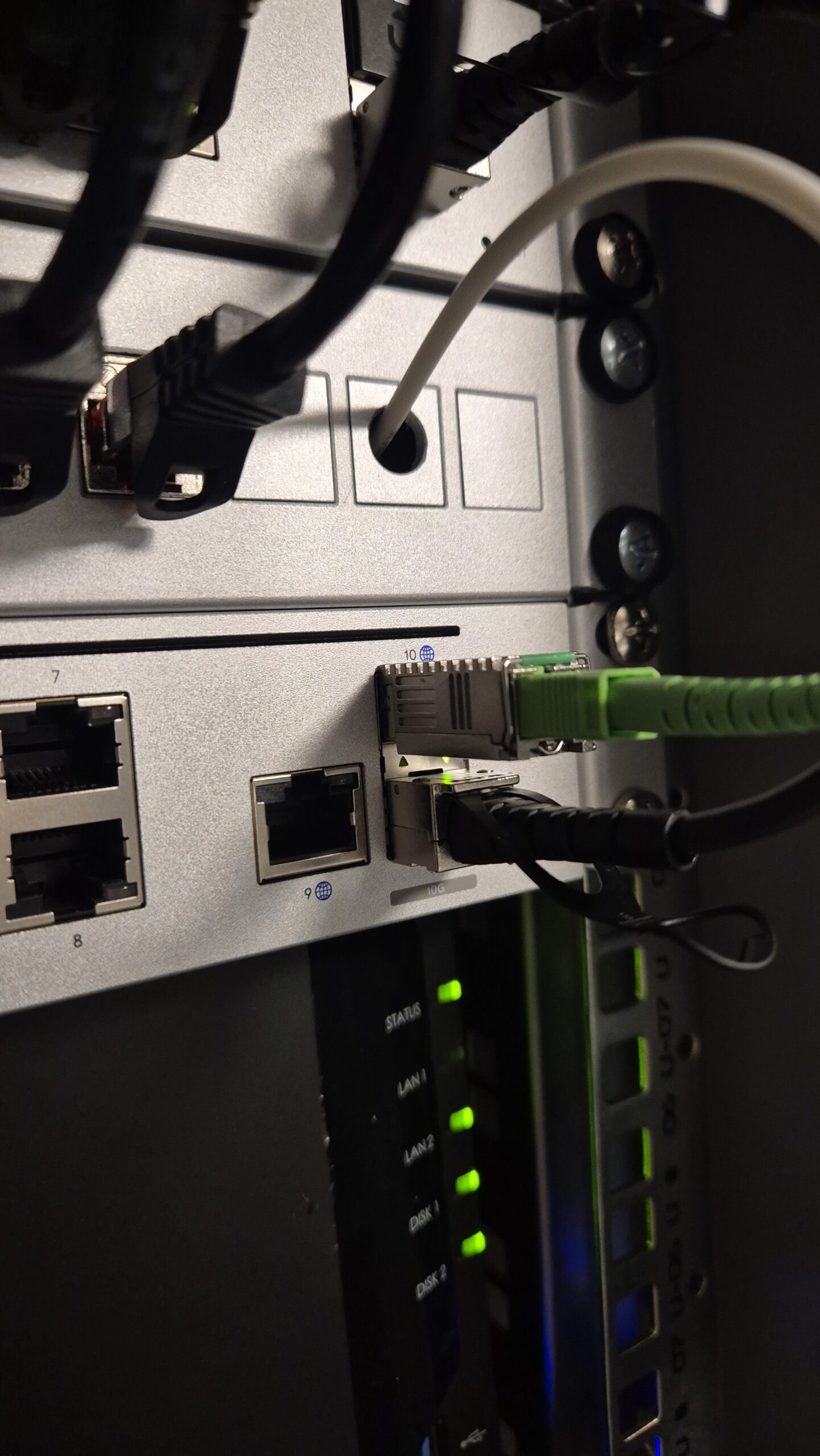
An XGS-PON ONU Stick contains PON functionality but still depends on its host for power, thermal conditions and the customer-side data path.
Do not infer compatibility from the SFP+ cage or the word “10G.” Verify:
- Exact host model, revision and port number
- Host ASIC, PHY and SerDes capabilities
- Host firmware, driver and port configuration
- Stick model, hardware and firmware
- Stick host-side mode and module coding
- Available power and cooling
- Actual negotiated host-side rate
- Maximum usable end-to-end throughput
A Stick can reach O5 while its host data path is down, rejected or operating incorrectly. A host can also read module EEPROM data without proving that the high-speed path works.
Keep these checkpoints separate:
PON optical state → PON activation state → OMCI/service state → host Ethernet state
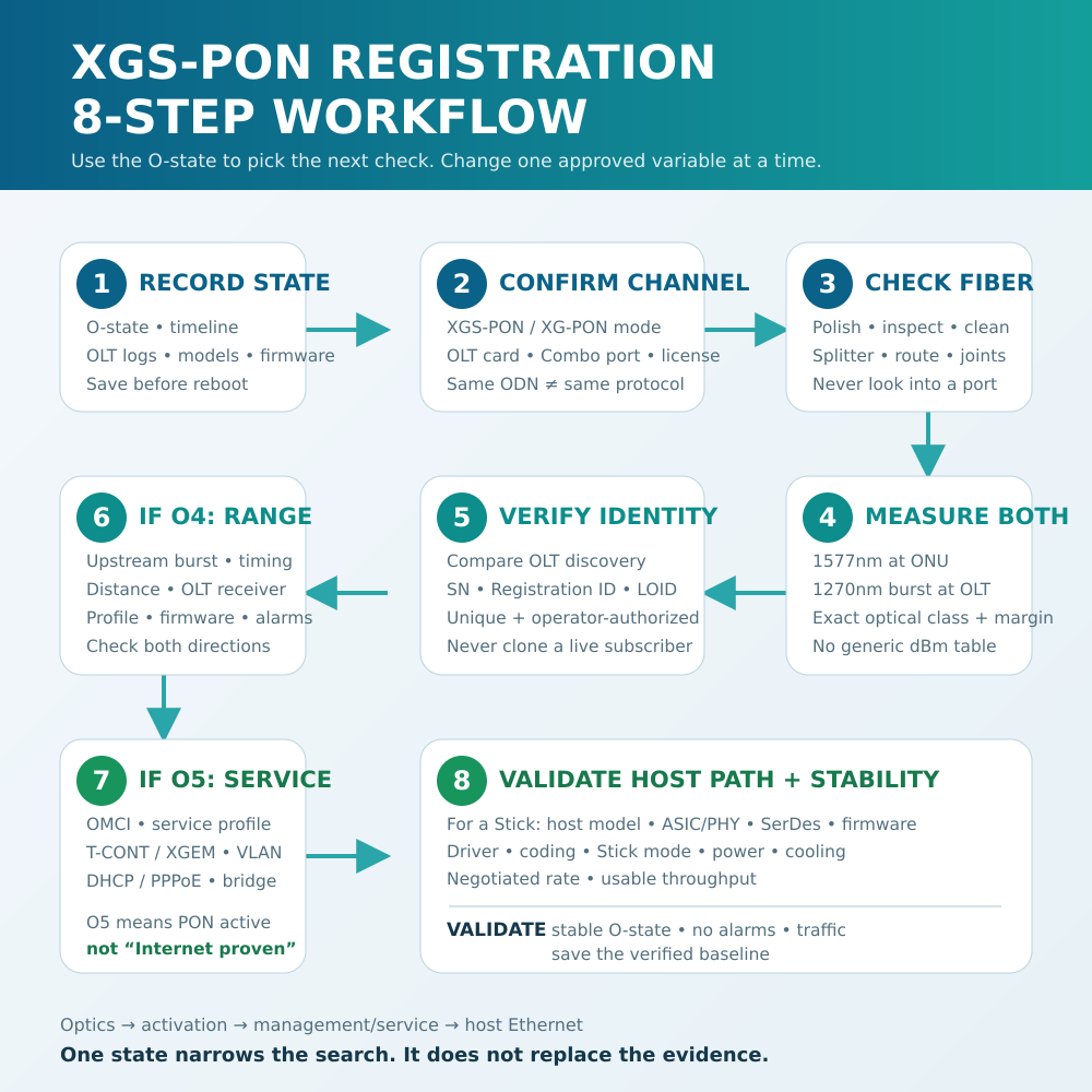
An Eight-Step XGS-PON Registration Workflow
Step 1: Capture the state and timeline
Record the O-state, how long it persists, all transitions, ONU model, firmware, OLT card, port, software and timestamp. Save OLT alarms before rebooting.
Step 2: Confirm the PON generation and channel
Verify that the subscriber uses an XGS-PON or supported XG-PON channel matching the ONU—not merely the same splitter used by GPON.
Step 3: Verify the physical interfaces
Match SC/APC to SC/APC or SC/UPC to SC/UPC. Never directly mate APC and UPC. Inspect and clean using approved tools, and never look into a fiber or port.
Step 4: Check both optical directions
Use exact optical-class limits and an instrument appropriate for the downstream channel and upstream burst. Include all fiber, splitter, connector, splice, coexistence-device and instrument losses.
Step 5: Verify authorized discovery data
Compare the identity detected by the OLT with the operator inventory. Check the required serial number, Registration ID, LOID or other approved fields without cloning another subscriber.
Step 6: Investigate ranging at O4
Check upstream burst reception, ranging alarms, distance, both loss windows, optical class, OLT profile and the exact ONU/OLT firmware combination.
Step 7: Move above the PON layer after O5
Verify OMCI, service profile, T-CONT/XGEM, VLAN, DHCP or PPPoE, operating mode and traffic. Stop changing optical settings when the evidence points to provisioning.
Step 8: Validate the host path and stability
For a Stick, confirm power, cooling, coding, SerDes mode, driver, negotiated rate and real traffic. Verify stable state and service over time.
Change one variable at a time. If the ONU moves from O3 to O4 after an authorized identity correction, that is useful evidence. If identity, attenuation, firmware and host port all change together, the result cannot identify the cause.
Applying the Workflow to the LuLeey LL-XS1010
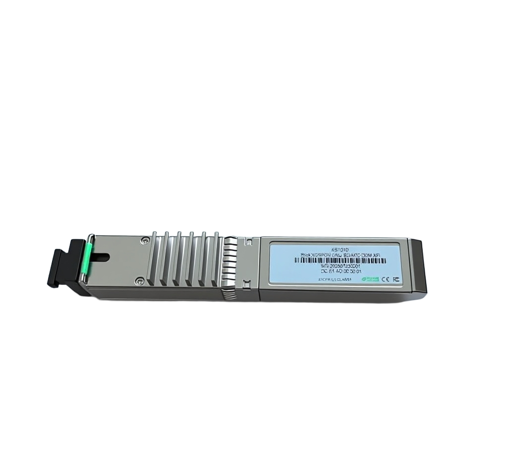
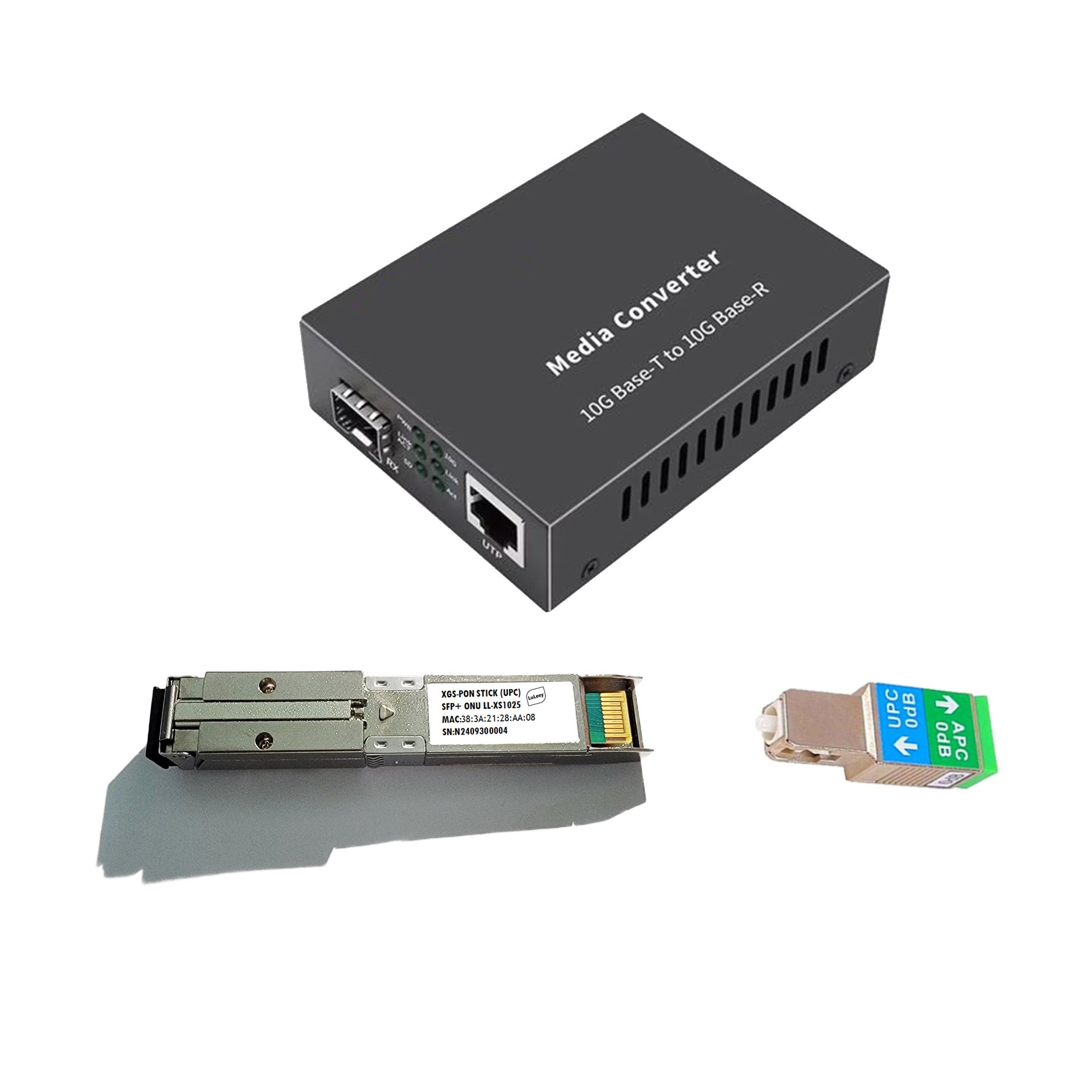
LuLeey’s LL-XS1010 XGS-PON/XG-PON ONU Stick page lists:
- MaxLinear PRX126 chipset and 1GB RAM
- XGS-PON/XG-PON support
- SFP+ package with SC/APC or SC/UPC options
- 1270nm burst-mode upstream and 1577nm downstream
- Listed 9.953Gb/s transmitter and receiver
- DDM support, 3.3V supply and about 3W power dissipation
- ITU-T G.988 OMCI
- Configurable PON identifiers and VLAN functions
The page also states that the product is not a universal plug-and-play replacement. Deployment depends on the ISP network, OLT and OMCI compatibility, authentication, VLAN settings, host support, power and cooling.
Its “Typical Optical Power Range” is not tied to a named optical class, OLT card, measurement point or uncertainty. Do not use that generic table as the acceptance rule for an unknown deployment. Obtain the exact ONU and OLT optical-class specifications.
Before asking LuLeey to diagnose registration failure, provide:
- O-state and timestamped transition history
- OLT vendor, card, port mode, software and alarms
- Stick model, hardware, firmware and OS build
- Authorized SN, Registration ID or LOID method
- Downstream and upstream burst readings with measurement method
- Splitter ratio, coexistence components, route and connector polish
- Host model, chipset/PHY, firmware, driver and port setting
- Module coding, Stick host mode, negotiated rate, power and temperature
- OMCI, T-CONT/XGEM, VLAN and DHCP/PPPoE results when O5 is reached
Final Answer
Use the highest stable O-state to choose the next test:
- O1: Verify the XGS-PON channel, downstream synchronization, optics and physical path.
- O2–O3: Inspect discovery, unique authorized identity, policy and interoperability.
- O4: Check upstream burst reception, ranging, timing and both optical windows.
- O5: Troubleshoot OMCI, XGEM/T-CONT, VLAN, DHCP/PPPoE and the host path.
- O6: Correlate intermittent downstream loss with optical, OLT, power and thermal trends.
- O7: Review the OLT disable reason and use the authorized re-enable procedure.
The state is not a diagnosis by itself. Pair it with OLT logs, optical-class data, controlled measurements and service tests.

 SFP/SFP+ (1G/2.5G/5G/10G)
 SFP-T (1G/2.5G/10G)
 AOC Cable 10G/25G/40G/100G
 DAC Cable 10G/25G/40G/100G
 QSFP28 QSFP+ SFP28 100G/40G/25G
 Copper to Fiber Media Converters
 Fiber Media Converter PCBA Board
 OEO Fiber Media Converters
 Serial to Fiber Media Converters
 Video to Fiber Media Converters
 1000M GPON/EPON ONU
 10G EPON ONU/XG-PON/XGS-PON
 2.5G GPON/XPON STICK SFP ONU
 POE GPON/EPON ONU
 Wireless GPON/EPON ONT
 EPON OLT
 GPON OLT
 SFP PON Module
 Industrial Switches
 Managed Switches
 POE Switches
 Unmanaged Switches
 MTP/MPO Fiber Cables
 Fiber Optic Cassettes
 Fiber Optic Loopback
 Optic Cables and Fiber Pigtails
 Optical Splitters and Splitter Box
 Fiber Flange Connectors
 Optical Adapters
 Optical Attenuator
 Quick Connector and Connector Panel
 CATV Amplifier
 CATV Optical Receiver
 Visual Fault Locator
 OTDR
OTDR Optical Power Meter
 Fiber Optic Identifier
 Fiber Optic Cleaners
 Fiber Cleavers & Fiber Strippers
 Copper Tools


