Customs duties are the responsibility of customers, but standard logistics support DDP to most countries, duty-free such as US, DE, UK, CA, FR, IT, PL, AT, JP…





















































Your SFP modules are detected and the fiber cable is connected, but the link light stays off. Before replacing the transceivers or patch cable, check the fiber Tx Rx polarity.
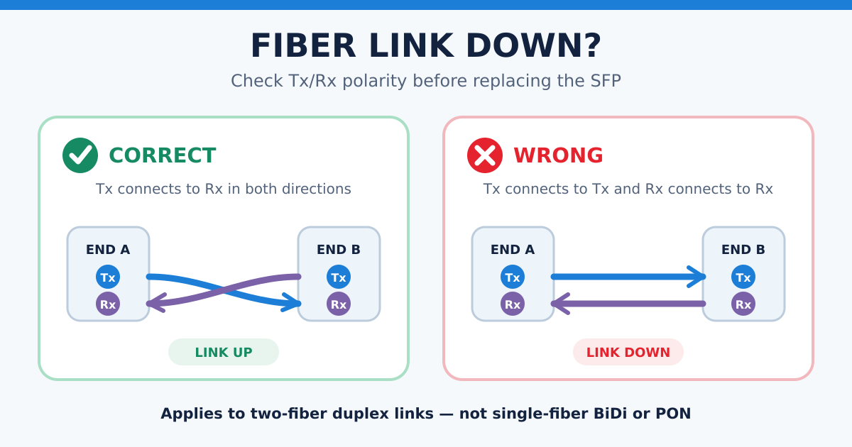
On a normal two-fiber connection:
- Local Tx must connect to remote Rx
- Local Rx must connect to remote Tx
If Tx connects to Tx and Rx connects to Rx, the link normally cannot be established.
The good news is that this problem usually takes only a few minutes to check.
Quick Answer
If you are using a Duplex LC or duplex SC connection, swap the two fiber strands at one end only.
- If the link comes up, the original polarity was reversed.
- If the link remains down, restore the original connection and continue checking the modules, fiber type, wavelength and optical power.
Do not use this method on single-fiber BiDi, PON, AOC or MPO connections.
Does This Test Apply to Your Fiber Link?
Use the strand-swap test only when your connection has:
- two separate fiber strands;
- a duplex optical interface, commonly duplex LC;
- one strand for transmitting;
- one strand for receiving.
A typical example is a switch-to-switch connection using two standard duplex SFP or SFP+ transceivers.
Do not swap strands in the following situations:
Single-fiber BiDi transceivers
A BiDi transceiver sends and receives over the same fiber using two different wavelengths. There are no separate Tx and Rx strands to swap.
Instead, confirm that the two BiDi modules use complementary Tx and Rx wavelengths.
For example, a module transmitting at 1270 nm must normally connect to a module receiving at 1270 nm and transmitting at the matching return wavelength.
See the LuLeey guide: SFP-10G-BX10-D vs SFP-10G-BX10-U.
GPON, EPON and XGS-PON
PON connections normally use one fiber for both downstream and upstream communication. A duplex strand-swap test does not apply.
AOC cables
The optical fibers and transceivers in an Active Optical Cable are factory-terminated as one complete assembly. The internal fiber paths cannot be reversed by the user.
MPO/MTP connections
MPO/MTP systems use multiple fibers and specific polarity methods. Do not randomly reverse individual fibers. Check whether the link requires Method A, Method B, Method C or a matching breakout configuration.
How to Check Fiber Tx/Rx Polarity
Step 1: Confirm that it is a two-fiber link
Look at the optical connection.
A duplex LC connection usually has two small LC connectors joined together. One fiber carries the signal in one direction, while the other fiber carries the return signal.
If the connection uses only one fiber, stop here. It may be a BiDi or PON link, and this test does not apply.
Step 2: Record the current connection
Take a photo or label the two fiber strands before changing anything.
This makes it easy to restore the original connection if the polarity is not the cause.
Do not look into an optical port or fiber connector. Optical signals may be invisible to the human eye. Follow the Fiber Optic Association’s fiber safety guidance.
Step 3: Swap the two strands at one end
Choose one end of the link and reverse the two fiber positions:
- Disconnect both fiber connectors carefully.
- Move the first strand into the position previously used by the second strand.
- Move the second strand into the first position.
- Reconnect both fibers fully.
- Leave the opposite end unchanged.
Only swap the strands at one end. Swapping both ends usually recreates the original polarity.
If the LC connectors are locked inside a fixed duplex clip, do not force the clip apart. Use a supported polarity-reversal mechanism, reverse the pair at a patch panel, or use a polarity-reversible duplex patch cable.
Step 4: Check the link indicator
Wait for the switch, router or network card to complete normal link initialization.
Then check the port status.
| Test result | What it means |
|---|---|
| Link comes up | The original Tx/Rx polarity was reversed |
| Link remains down | Polarity may not be the main problem |
| Link repeatedly goes up and down | Check connector cleanliness, optical power and port settings |
| Only one side receives optical power | Check the return strand, connector and remote transmitter |
The FOA link polarity guide explains why fiber links must maintain the correct transmit-to-receive path. The public IETF RFC 5171 also describes how incorrect fiber patching can create an invalid or one-way communication path.

What Should You Do If the Link Comes Up?
If the link works after swapping the two strands:
- Keep the working polarity.
- Label both strands.
- Record the connection at both ends.
- Secure the cable without creating tight bends.
- Confirm that the link speed is correct.
- Check for packet errors or unstable operation.
You do not necessarily need to replace the cable. However, use a properly wired or polarity-reversible patch cable if the current connection requires forcing, dismantling or leaving connectors unsecured.
What If Swapping Tx/Rx Does Not Fix the Link?
Restore the original connection and check the following items in order.
1. Are both ports enabled?
Confirm that neither optical port has been disabled in the switch, router or network card settings.
2. Do both sides use the same data rate?
A 1G transceiver and a 10G transceiver normally cannot establish a standard Ethernet link with each other.
Also check whether the host port supports the required speed. The words SFP, SFP+ or SFP28 alone do not guarantee every intermediate speed.
3. Do the transceivers use compatible optical standards?
Both sides must use compatible:
- data rates;
- wavelengths;
- transmission distances;
- fiber types;
- optical standards.
Do not assume that two modules are compatible simply because both have LC connectors.
4. Is the fiber type correct?
Use single-mode fiber with single-mode transceivers.
Use the correct multimode fiber with multimode transceivers. OM1, OM2, OM3, OM4 and OM5 do not offer the same transmission performance at every speed and distance.
5. Are the connectors clean?
Dust and contamination can increase insertion loss.
Do not touch the connector end face. If cleaning is required, use proper fiber-optic cleaning tools instead of ordinary tissues, clothing or compressed air of unknown cleanliness.
6. Is the cable sharply bent or damaged?
Check whether the cable is:
- trapped under furniture;
- bent around a sharp corner;
- pulled too tightly;
- squeezed by a cable tie;
- damaged near the connector.
Keep the fiber in smooth, relaxed curves.
7. Is the received optical power within range?
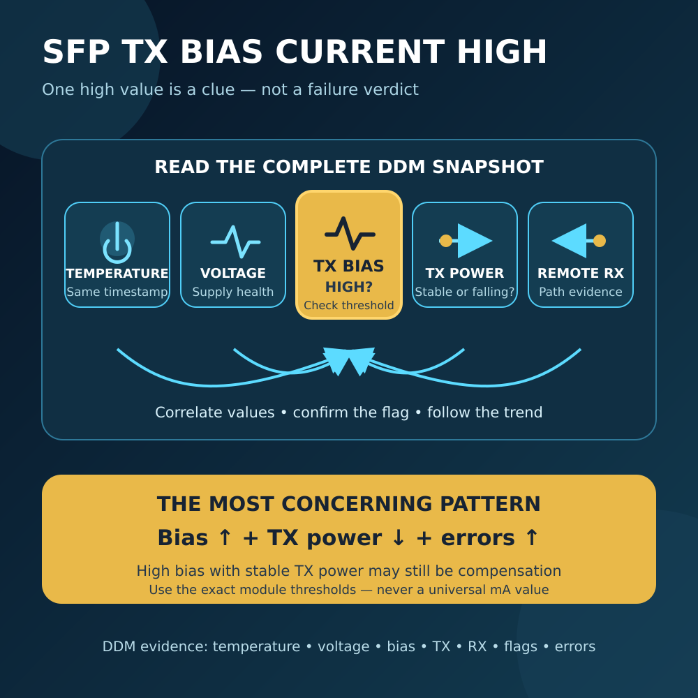
If the device supports DDM or DOM, check the reported Tx and Rx optical power.
Compare the received power with the receiver range specified for the transceiver. Too little optical power can cause no link, while excessive power can overload the receiver on some short single-mode connections.
The FOA fiber network troubleshooting guide recommends checking receiver power, transmitter power, transceivers and link loss when diagnosing optical network problems.
If DDM information is unavailable, use an optical power meter and the correct test procedure. The FOA fiber optic testing guide explains the basic relationship between transmitter power, receiver power and link loss.
A Simple Example
Two switches are connected using duplex LC SFP+ transceivers.
Both switches detect their transceivers, but the link indicators remain off.
The cable path currently connects:
- Switch A Tx → Switch B Tx
- Switch A Rx ← Switch B Rx
Neither receiver is connected to the opposite transmitter.
After swapping the two strands at Switch B only, the path becomes:
- Switch A Tx → Switch B Rx
- Switch A Rx ← Switch B Tx
The link can now come up, provided that the transceivers, speed, wavelength, fiber type and optical power are also compatible.
Final Checklist
When a new duplex fiber link stays down:
- Confirm that it is a two-fiber duplex link.
- Take a photo of the original connection.
- Never look into an optical port.
- Swap the two strands at one end only.
- Check whether the link comes up.
- If it remains down, restore the original connection.
- Check port status, module rate, wavelength and fiber type.
- Clean and reseat the connectors correctly.
- Check the cable for sharp bends or damage.
- Measure or review the received optical power.
Before selecting new transceivers or patch cables, read the LC vs SC vs MPO connector guide or browse LuLeey’s optical module transceivers.
 SFP/SFP+ (1G/2.5G/5G/10G)
 SFP-T (1G/2.5G/10G)
 AOC Cable 10G/25G/40G/100G
 DAC Cable 10G/25G/40G/100G
 QSFP28 QSFP+ SFP28 100G/40G/25G
 Copper to Fiber Media Converters
 Fiber Media Converter PCBA Board
 OEO Fiber Media Converters
 Serial to Fiber Media Converters
 Video to Fiber Media Converters
 1000M GPON/EPON ONU
 10G EPON ONU/XG-PON/XGS-PON
 2.5G GPON/XPON STICK SFP ONU
 POE GPON/EPON ONU
 Wireless GPON/EPON ONT
 EPON OLT
 GPON OLT
 SFP PON Module
 Industrial Switches
 Managed Switches
 POE Switches
 Unmanaged Switches
 MTP/MPO Fiber Cables
 Fiber Optic Cassettes
 Fiber Optic Loopback
 Optic Cables and Fiber Pigtails
 Optical Splitters and Splitter Box
 Fiber Flange Connectors
 Optical Adapters
 Optical Attenuator
 Quick Connector and Connector Panel
 CATV Amplifier
 CATV Optical Receiver
 Visual Fault Locator
 OTDR
OTDR Optical Power Meter
 Fiber Optic Identifier
 Fiber Optic Cleaners
 Fiber Cleavers & Fiber Strippers
 Copper Tools


