Customs duties are the responsibility of customers, but standard logistics support DDP to most countries, duty-free such as US, DE, UK, CA, FR, IT, PL, AT, JP…





















































Fiber Media Converter lights on but No Network describes a common fault pattern: several green LEDs appear, yet the far endpoint still cannot communicate. Do not assume the complete path is working. One light may confirm power, a local copper link, or received optical signal. It may say nothing about traffic reaching the far endpoint, the return direction, VLAN membership, DHCP, PPPoE, or the IP gateway.
The fastest approach is to draw the full path and find the first layer where the evidence changes:
Endpoint A → copper → converter A → fiber → converter B → copper → endpoint B
Check both directions and change one item at a time. This avoids replacing a converter when the real problem is a mismatched BIDI pair, a forced Ethernet mode, a blocked VLAN, or an IP configuration issue.
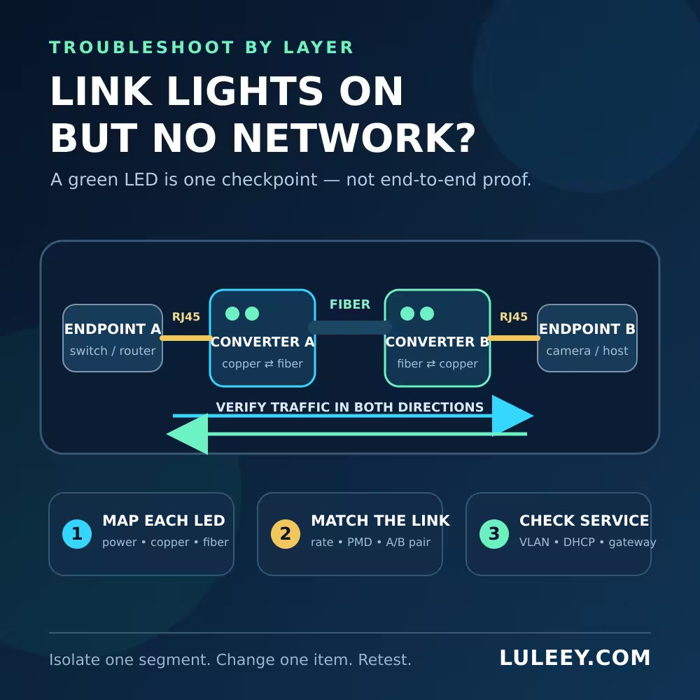
Fiber Media Converter Lights On but No Network: Start Here
First, identify what each LED means for the exact converter model and revision. Labels such as PWR, TP, FX, LINK, ACT, FDX and SPD are not interpreted identically by every product.
Create a simple table before touching the link:
| Segment | Evidence to record | What it does not prove |
|---|---|---|
| Power | Correct adapter, stable power LED | Correct voltage under load or healthy data path |
| Copper A | Link and actual rate at endpoint A and converter A | Fiber or far-end copper is working |
| Fiber | Optical-link indication, if the model provides one | Clean frames, return traffic, or IP service |
| Copper B | Link and actual rate at converter B and endpoint B | VLAN, addressing or application reachability |
Photograph the LEDs and labels, and note whether they are steady or flashing. Do not infer the meaning of an unlabeled light from its color.
1. Verify Power and Both Copper Links
Check the power supply specified for each converter. The plug may fit while the voltage, polarity or available current is wrong. An unstable supply can also create repeated link events rather than a permanent power failure.
Then inspect the two copper segments separately. Confirm the actual operating rate reported at both endpoints. A device marketed as “Gigabit” does not guarantee that every attached port is currently running at 1 Gbps.
If speed and duplex are configurable, begin with a supported, consistent configuration. Forcing one side while leaving the other side to negotiate can produce a link that behaves poorly. Do not change speed, duplex, flow control and cabling at the same time; save a baseline and make one controlled change.
Substitute one known-good, correctly rated copper patch lead if the evidence points to a copper leg. Keep the complete copper channel within the requirements of the selected Ethernet mode.
2. Match the Optical Path, Not Just the Connector
An SC or LC plug that fits does not establish optical compatibility. Verify:
- Ethernet PMD and actual operating rate at both optical ends
- Single-mode or multimode fiber
- Connector family and polish; do not mate APC and UPC
- Transmit and receive wavelengths
- Duplex-fiber TX-to-RX polarity, or the correct single-fiber BiDi A/B pair
- Route loss against the exact receivers’ minimum and maximum operating inputs
The IEEE 802.3-2022 standard record covers distinct Ethernet physical layers for different media and rates. The converter and transceiver data sheets still determine which combination a particular product supports.
For duplex fiber, local TX must reach remote RX in each direction. If the Fiber Link does not establish, reverse the duplex pair only as a documented polarity test; do not randomly move production fibers.
For single-fiber BiDi, the two ends normally use complementary wavelengths. Two units with the same transmit/receive direction may power up yet never form a normal optical pair.
Inspect and clean accessible connectors with approved equipment. The Fiber Optic Association connector guide explains why contamination can transfer between mated ferrules. Never look into a fiber or optical port; confirm power status and use an appropriate video inspection method.
Do not approve a link from a generic dBm range. Compare each direction with the exact transmitter and receiver specifications, including diagnostic accuracy where DDM is available.
3. Check Whether Frames Pass in Both Directions
When all link indications are present, stop staring at the LEDs and look for changing counters.
Take time-stamped snapshots at the two endpoint ports before and after a short, authorized test. Record transmitted and received frames, FCS/CRC errors, drops, link events and the actual rate. Use counter deltas, not an old cumulative total.
| Observation | Likely fault domain to test next |
|---|---|
| Endpoint A transmits, but endpoint B receives nothing | A-to-B copper, converter, optical direction, or B-side receive path |
| Traffic works one way only | Treat the two directions separately; check polarity, BiDi pairing and the affected receiver path |
| Both endpoints exchange frames, but no IP address appears | Move to VLAN, DHCP, PPPoE or IP configuration |
| Frames pass, but FCS/CRC errors rise | Check the receiving direction, optics, cabling and host port; Link Up is not enough |
| Link repeatedly goes down and up | Check power, cable seating, temperature, rate/mode support and the physical path |
If errors rise while RX power appears normal, use LuLeey’s SFP CRC troubleshooting guide to follow the bad-frame direction without declaring the optic faulty from one reading.
4. Confirm What the Converter Can Actually Convert
Some media converters bridge one Ethernet mode between copper and fiber. Others contain a switch function or support several host-side rates. Do not assume that every device performs arbitrary rate conversion just because both links show green.
For a fixed-optics converter, verify the built-in optical PMD and the copper modes. For an SFP-based converter, also check the exact module, module coding, converter chipset/PHY, firmware, slot electrical mode and port settings.
An SFP, SFP+ or SFP28 name describes a form-factor family, not a complete compatibility result. Physical fit, host SerDes mode, negotiated or configured rate, and usable throughput are separate checks.
The same caution applies to a 2.5G PON ONU Stick. A port marked 1G or 10G may operate with the Stick at 1G only when both sides support a compatible 1G host mode; some SFP+ hosts may support 2.5G with the right chipset, PHY, firmware and settings. Verify the exact converter model, host mode, module coding, firmware/driver and observed rate instead of deciding from the cage label.
5. Check VLAN and Network Service After Frames Pass
A basic unmanaged media converter normally does not create an IP address, route between subnets or fix a VLAN mismatch. Once frames pass both ways, keep moving up the stack.
Check:
- Access versus tagged VLAN expectations at both endpoint ports
- Whether a managed converter or switch is filtering the required VLAN
- STP, link aggregation, port security or loop-protection state
- DHCP or PPPoE availability on the intended VLAN
- Static IP address, subnet mask, default gateway and DNS settings
- Whether a hostname or test device is using a different interface, such as Wi-Fi
IEEE 802.1Q defines bridged networks and VLANs; the IEEE 802.1Q-2022 record is the relevant standards reference. A physical link indication cannot prove that two ports belong to the same forwarding service.
When testing, use the intended wired IP address and a known endpoint on the same service. A failed Internet test alone cannot distinguish the converter from the router, DNS, firewall or upstream provider.
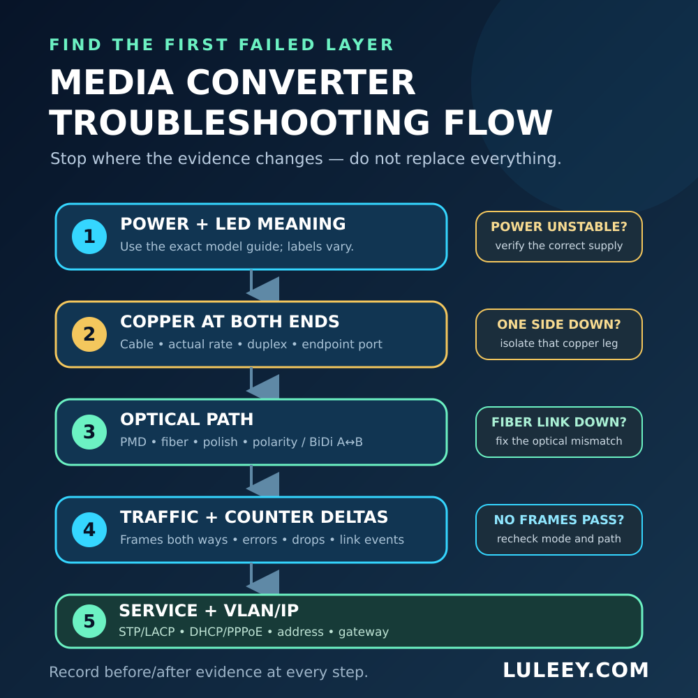
6. Isolate the First Failed Segment
Use the least disruptive test that removes one unknown:
- Save the original topology, settings, LED state and counters.
- Confirm stable power and both copper links.
- Verify optical PMD, fiber, polish, polarity or BiDi pairing, and power limits.
- Check whether frames and counter changes appear at both endpoints.
- If frames pass, test VLAN and IP service rather than replacing optics.
- Substitute only one known-good, correctly specified component in an approved maintenance window.
- Repeat the same observation and restore the approved configuration when finished.
A local direct test can narrow the problem, but it does not certify the production route. Likewise, a converter that works on a bench with different endpoints is not automatically compatible with the original port modes and service design.
Where LuLeey Media Converters Fit
LuLeey’s copper-to-fiber media converter range includes fixed-optics and pluggable-module designs at different rates. Choose by the complete path, not by connector appearance alone.
For a specific example, the LL-BDMC1000 fixed SC BiDi converter lists a single-mode SC/UPC optical interface, a complementary 1310/1550 nm A/B pair and up to 20 km reach. It is a fixed-optics converter, not an SFP cage, and it must not be treated as a host for a PON ONU Stick.
The page currently gives two different copper-rate descriptions—10/100/1000 Mbps in one section and 100/1000M adaptive in its specification table. Confirm the exact hardware revision and supported copper modes with LuLeey before purchase or deployment. The page also does not publish a complete optical power window, so its distance label alone is not an acceptance test for a particular route.
 SFP/SFP+ (1G/2.5G/5G/10G)
 SFP-T (1G/2.5G/10G)
 AOC Cable 10G/25G/40G/100G
 DAC Cable 10G/25G/40G/100G
 QSFP28 QSFP+ SFP28 100G/40G/25G
 Copper to Fiber Media Converters
 Fiber Media Converter PCBA Board
 OEO Fiber Media Converters
 Serial to Fiber Media Converters
 Video to Fiber Media Converters
 1000M GPON/EPON ONU
 10G EPON ONU/XG-PON/XGS-PON
 2.5G GPON/XPON STICK SFP ONU
 POE GPON/EPON ONU
 Wireless GPON/EPON ONT
 EPON OLT
 GPON OLT
 SFP PON Module
 Industrial Switches
 Managed Switches
 POE Switches
 Unmanaged Switches
 MTP/MPO Fiber Cables
 Fiber Optic Cassettes
 Fiber Optic Loopback
 Optic Cables and Fiber Pigtails
 Optical Splitters and Splitter Box
 Fiber Flange Connectors
 Optical Adapters
 Optical Attenuator
 Quick Connector and Connector Panel
 CATV Amplifier
 CATV Optical Receiver
 Visual Fault Locator
 OTDR
OTDR Optical Power Meter
 Fiber Optic Identifier
 Fiber Optic Cleaners
 Fiber Cleavers & Fiber Strippers
 Copper Tools


