Customs duties are the responsibility of customers, but standard logistics support DDP to most countries, duty-free such as US, DE, UK, CA, FR, IT, PL, AT, JP…





















































You can connect SC/APC to an LC/UPC SFP with a single-mode Hybrid Patch Cable: SC/APC on the FTTH side and LC/UPC on the SFP side. The two polish types can exist at opposite ends of one cable because they never touch each other.
What you must not do is mate an APC ferrule directly against a UPC ferrule in a standard coupler. Their end-face geometries do not match, which can create high loss, strong reflection, an unstable link and possible surface damage.

The Correct SC/APC-to-LC/UPC Connection
Use this topology:
SC/APC port → SC/APC connector — single-mode fiber — LC/UPC connector → LC/UPC SFP port
Each physical connection remains correctly matched:
- The green SC/APC cable end mates with the SC/APC FTTH port.
- The blue LC/UPC cable end mates with the LC/UPC optical transceiver.
- APC and UPC are separated by the fiber inside the patch cable; their polished faces are not pressed together.
This assembly is normally called an SC/APC-to-LC/UPC hybrid fiber patch cable. “Hybrid” means its two ends use different connector formats or polish types. It does not mean that incompatible ferrules are directly mated.
The Fiber Optic Association gives the same practical solution for links containing APC patch-panel connections and UPC equipment connections: use a hybrid patch cord so that the APC end meets APC and the UPC end meets UPC.
Why Direct APC-to-UPC Mating Is Wrong
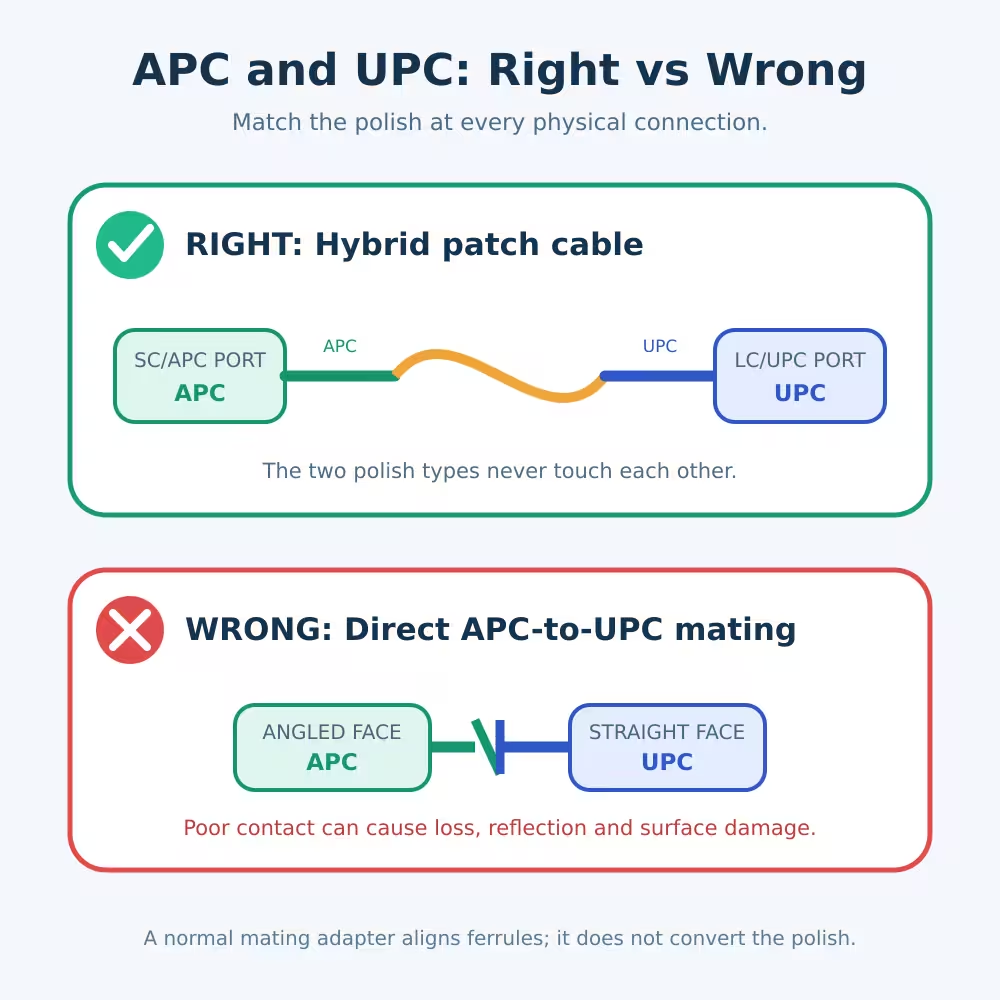
UPC and APC describe the geometry of the polished fiber end face.
- A UPC ferrule has a convex end face polished perpendicular to the fiber axis.
- An APC ferrule is polished at an angle and is commonly identified by a green connector body or boot.
When an APC connector is pushed directly against a UPC connector, the surfaces do not make the intended full physical contact. Light can be lost or reflected at the gap, and pressure may be concentrated on the wrong part of the ferrule surface.
A coupler does not convert the polish. A normal SC-to-SC or LC-to-LC mating adapter only aligns two ferrules. If one ferrule is APC and the other is UPC, the adapter still pushes incompatible end faces toward each other.
The safe rule is simple:
At every physical mating point, match APC with APC and UPC with UPC.
Connector color is a useful first check—APC is commonly green and UPC is commonly blue—but color alone is not final proof. Check the port label, equipment manual, product specification or ferrule end face before connecting.
What the Hybrid Patch Cable Does—and Does Not Do
The cable changes the connector presented at each end. It does not convert the optical protocol.
A passive SC/APC-to-LC/UPC patch cable does not change:
- GPON into Ethernet
- XGS-PON into ordinary 10G Ethernet
- One wavelength into another wavelength
- Single-fiber BiDi into dual-fiber transmission
- Transmitter power into a safe receiver level
- An incompatible ONU or SFP into a compatible device
For example, an SC/APC wall outlet carrying GPON cannot be connected to an ordinary Ethernet SFP simply because the connectors fit. The receiving device still needs the correct PON ONU/ONT function, wavelength plan, registration method and optical power range.
Likewise, a BiDi Ethernet link needs the correct complementary wavelength pair. The patch cable only provides the physical optical path.
How to Choose the Right SC/APC-to-LC/UPC Cable
1. Confirm both equipment ports
Do not choose the cable from the existing cable colors alone. Identify the exact ports:
- FTTH outlet, splitter, patch panel or ODF: SC/APC female?
- SFP, SFP+, ONU stick, media converter or test device: LC/UPC female?
If the transceiver has duplex LC, determine whether the link uses both fibers or only one. A dual-fiber transceiver normally requires two optical paths, while a simplex BiDi transceiver uses one.
2. Match the polish at each port
The connector inserted into an SC/APC port must be SC/APC. The connector inserted into an LC/UPC port must be LC/UPC.
Do not substitute SC/UPC at the FTTH end merely because SC/UPC and SC/APC share the same outer connector shape.
3. Choose the correct fiber mode
For typical FTTH and long-reach single-mode transceivers, use a single-mode cable matching the installed link. Do not mix a multimode patch cable into a single-mode path simply because the connector fits.
Also check whether the installation specifies bend-insensitive fiber, especially for indoor FTTH routing.
4. Choose simplex or duplex correctly
Use simplex for a single-fiber optical path, such as many PON and BiDi connections. Use duplex when the equipment requires separate transmit and receive fibers.
The number of LC connectors is a useful clue, but the exact transceiver specification is the final reference.
5. Check wavelength and protocol
Connector compatibility does not prove system compatibility. Verify:
- Optical protocol
- Transmit and receive wavelengths
- Single-fiber or dual-fiber operation
- Supported distance
- Transmitter output range
- Receiver sensitivity and overload limit
- Equipment and network registration requirements
6. Select a practical cable length
Avoid a cable that must be pulled tight, sharply bent or tightly coiled behind equipment. Leave enough slack for routing and servicing while keeping excess cable organized.
LuLeey’s SC, LC, FC, UPC and APC single-core patch cable page lists single-mode, single-core options with configurable connector types and lengths. Confirm the required Connector A and Connector B combination before ordering.
Installation Steps
Step 1: Follow the equipment procedure
Power down when the equipment manufacturer requires it. Never look into an active Fiber Connector or optical port. Invisible infrared light can be hazardous to the eye.
Step 2: Verify the labels
Before removing dust caps, confirm:
- SC/APC at the FTTH side
- LC/UPC at the SFP side
- Single-mode fiber
- Simplex or duplex construction
- Correct optical system and wavelength
Step 3: Inspect and clean both ends
Dirty connectors are a common cause of high loss and reflection. Inspect with suitable fiber-scope procedures and clean with tools designed for the connector type.
Never inspect a connector until you have confirmed that hazardous optical power is not present.
Clean before every connection, including a new cable. A clean connector can be contaminated by mating with a dirty adapter or port.
Step 4: Connect each end without twisting
Insert the SC/APC end into the matching SC/APC port and the LC/UPC end into the matching LC/UPC port. Align the key correctly and do not force a connector that does not seat normally.
Step 5: Route the cable safely
Protect the cable from tight bends, doors, chair wheels, excessive tension and cable ties pulled too tightly. Follow the cable manufacturer’s minimum bend-radius requirement.
Step 6: Check the optical link
Verify link status and optical power after connection. If the module supports DDM/DOM, compare its RX power with the receiver limits for that exact module.
For PON equipment, check both the ONU/ONT optical reading and registration state.
Troubleshooting: Connected but No Link
Are the polish types matched at both ports?
Make sure the green SC/APC end is not connected to a blue SC/UPC port and that the LC end matches the SFP’s specified polish.
Is the cable simplex or duplex?
A dual-LC transceiver may require separate TX and RX fibers. A simplex cable cannot replace a required duplex path.
Is polarity correct?
For a dual-fiber link, TX on one device must reach RX on the other. If the link is dark, check the two-fiber polarity before assuming that the module is faulty.
Do the wavelengths match?
For BiDi modules, the endpoints need complementary transmit and receive wavelengths. Two identical “U” or two identical “D” modules normally do not form a working pair.
Is the signal within the receiver range?
Measure or read the received optical power and compare it with the exact receiver specification. A signal can fail because it is too weak or because it overloads the receiver.
Is this the correct protocol?
An Ethernet SFP cannot replace a GPON or XGS-PON ONU simply because both use an LC or SC fiber connection. Confirm the device function and network protocol.
Are the connectors clean?
Reinspect and clean the connectors and adapter sleeves using approved procedures. Replace a visibly scratched or damaged patch cable instead of repeatedly reconnecting it.
For more background about end-face polish and reflection, read LuLeey’s guide to PC, UPC and APC fiber patch cords.
Can You Use a Small APC-to-UPC Converter Instead?
Be careful with the word “converter.” A simple mating sleeve cannot correct incompatible ferrule geometry.
Some specialized male-to-female optical conversion devices use an internal optical structure rather than directly mating an APC ferrule with a UPC ferrule. Their loss, return loss, wavelength range, direction and application must be verified individually.
For permanent or performance-sensitive links, a factory-terminated hybrid patch cable is usually the clearest solution because every equipment port receives the correct matching connector.
Do not assume that every product labeled “APC-to-UPC adapter” is equivalent to a hybrid patch cable.
Final Answer
To connect an SC/APC FTTH interface to an LC/UPC SFP, use a single-mode hybrid patch cable with SC/APC on the FTTH end and LC/UPC on the SFP end.
The different polish types are safe at opposite ends of the cable. They should not be mated directly against each other in a normal adapter.
Before ordering, confirm the port polish, simplex or duplex construction, fiber mode, protocol, wavelengths, optical power range, cable length and equipment compatibility.
If you send LuLeey clear photos of both port labels together with the exact device and transceiver models, the required Connector A and Connector B configuration can be checked before production.
 SFP/SFP+ (1G/2.5G/5G/10G)
 SFP-T (1G/2.5G/10G)
 AOC Cable 10G/25G/40G/100G
 DAC Cable 10G/25G/40G/100G
 QSFP28 QSFP+ SFP28 100G/40G/25G
 Copper to Fiber Media Converters
 Fiber Media Converter PCBA Board
 OEO Fiber Media Converters
 Serial to Fiber Media Converters
 Video to Fiber Media Converters
 1000M GPON/EPON ONU
 10G EPON ONU/XG-PON/XGS-PON
 2.5G GPON/XPON STICK SFP ONU
 POE GPON/EPON ONU
 Wireless GPON/EPON ONT
 EPON OLT
 GPON OLT
 SFP PON Module
 Industrial Switches
 Managed Switches
 POE Switches
 Unmanaged Switches
 MTP/MPO Fiber Cables
 Fiber Optic Cassettes
 Fiber Optic Loopback
 Optic Cables and Fiber Pigtails
 Optical Splitters and Splitter Box
 Fiber Flange Connectors
 Optical Adapters
 Optical Attenuator
 Quick Connector and Connector Panel
 CATV Amplifier
 CATV Optical Receiver
 Visual Fault Locator
 OTDR
OTDR Optical Power Meter
 Fiber Optic Identifier
 Fiber Optic Cleaners
 Fiber Cleavers & Fiber Strippers
 Copper Tools


