Customs duties are the responsibility of customers, but standard logistics support DDP to most countries, duty-free such as US, DE, UK, CA, FR, IT, PL, AT, JP…

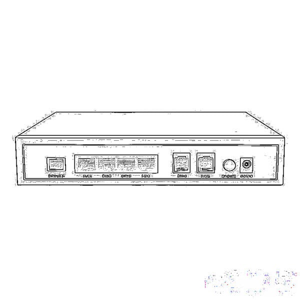
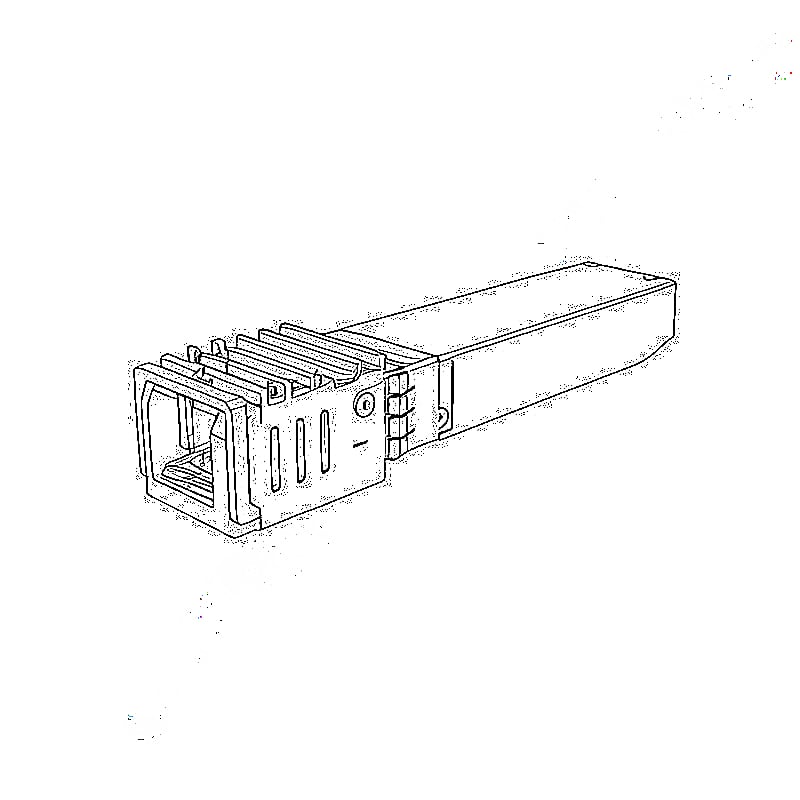
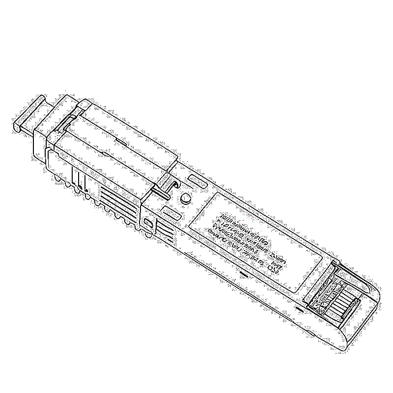
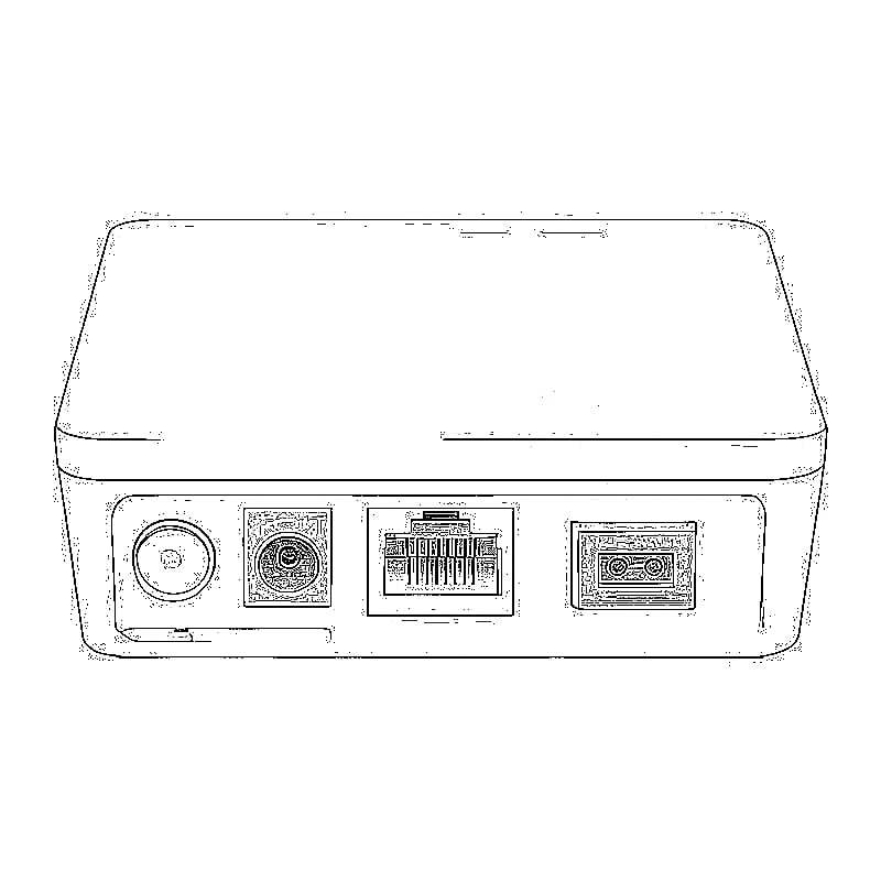
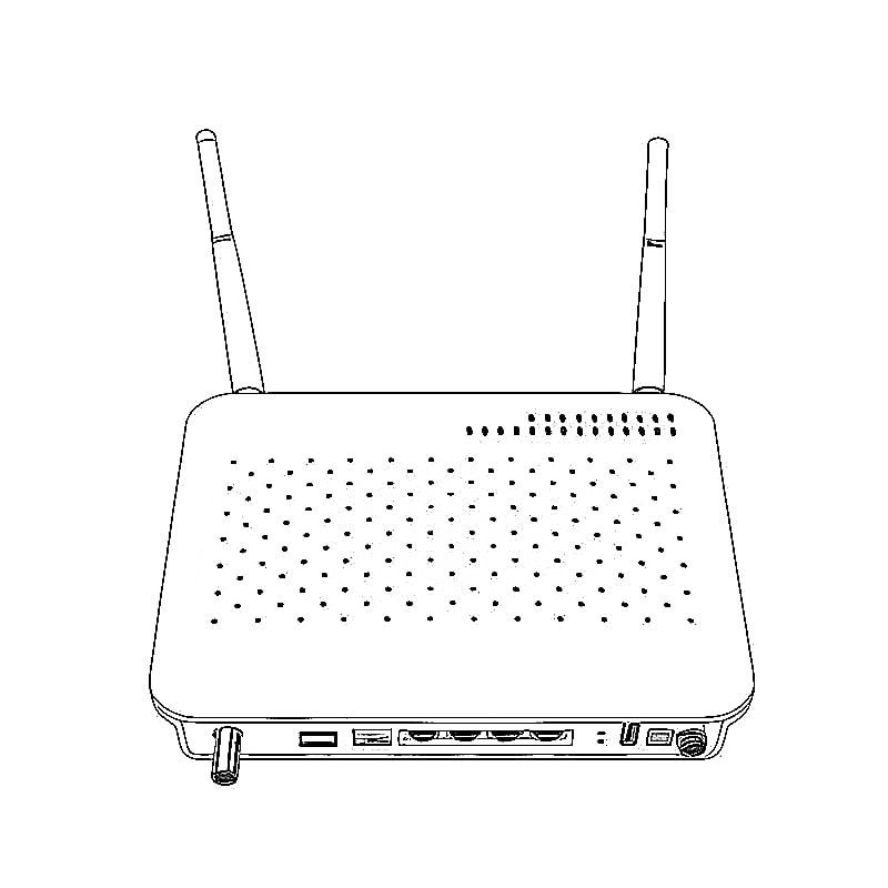
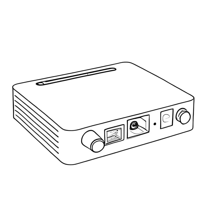
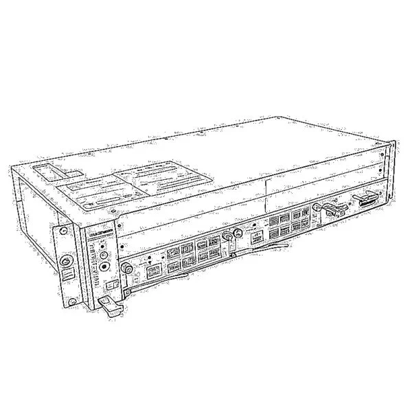
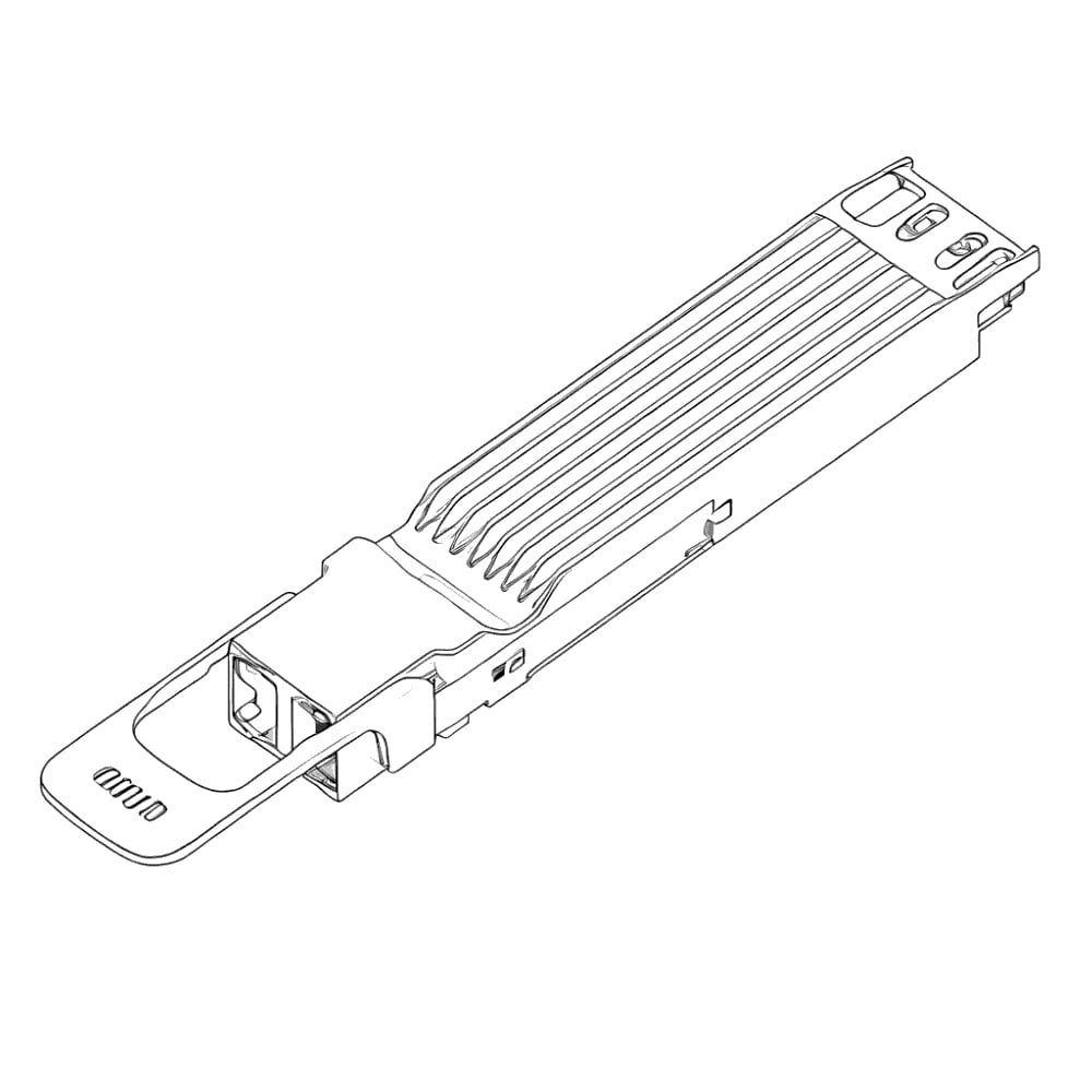
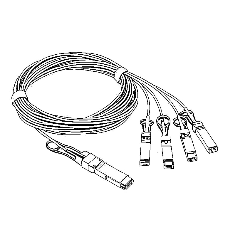
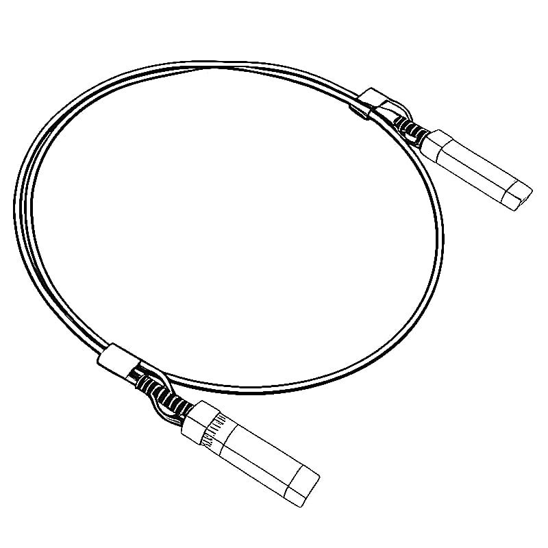
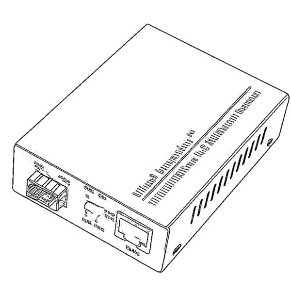
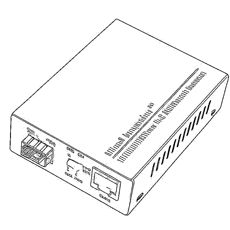
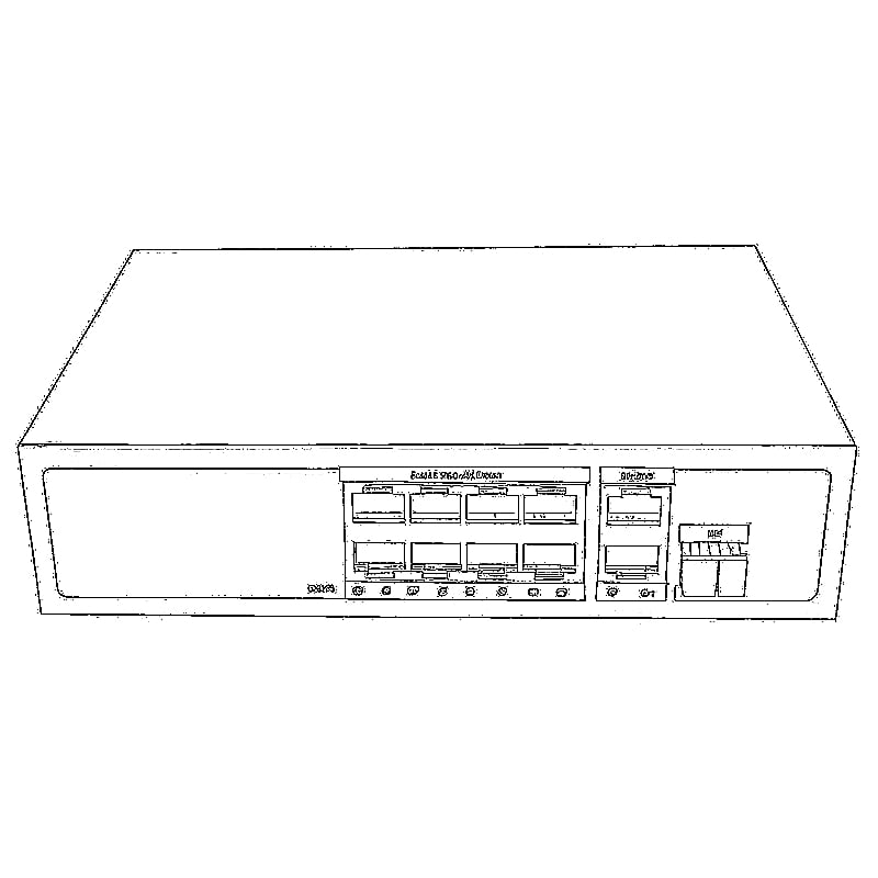
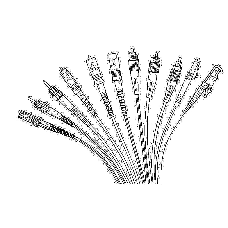

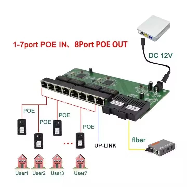
POE over fiber usually means carrying Ethernet data over a fiber link, then supplying Power over Ethernet on copper cable at the remote end. It does not mean that an ordinary optical SFP sends electrical PoE through the fiber.
That distinction matters when connecting a camera at a gate, an access point in a detached building, or several devices in a remote equipment room. Fiber can solve the data-distance problem while leaving the power problem unsolved.
Before buying a converter, answer one question: what will power the equipment at the far end?
PoE over Fiber: Two Paths to Plan
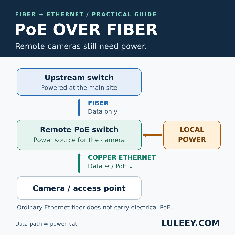
Draw the data route and the power route separately.
- Data: main-site switch → optical fiber → remote Ethernet equipment → camera or AP.
- Power: remote electrical supply → PoE-capable equipment → copper cable → camera or AP.
The arrows show the connection sequence; Ethernet data travels both ways. Electrical PoE flows from the power source toward the powered device.
The source is called PSE, or power sourcing equipment. The camera or AP is the PD, or powered device. IEEE PoE uses copper conductors; an ordinary Ethernet optical link does not transport that electrical supply. The FOA PoE overview explains switch-based and separate midspan power delivery.
A PoE switch at the main site does not remove the remote power requirement simply because its uplink uses fiber.
Three Practical Remote-End Designs
The following are generic design options, not a claim that every converter supports PoE.
1. A PoE switch with an optical uplink
Use a locally powered switch whose designated copper ports provide the required PoE output. Connect its optical uplink to the main site, then connect the cameras or APs to its PoE ports.
This is a useful layout when several devices share one remote location. Check the individual port limits, total power budget and uplink capacity separately.
2. A MEDIA CONVERTER with a PoE PSE output
A suitable PoE media converter combines fiber-to-copper data conversion with power injection on its RJ45 output. It still needs an electrical supply.
Look for an explicit PoE output/PSE specification. “PoE-powered,” “PoE input” or “PD” may instead describe how the converter receives its own power. Those labels do not establish that it can power a camera.
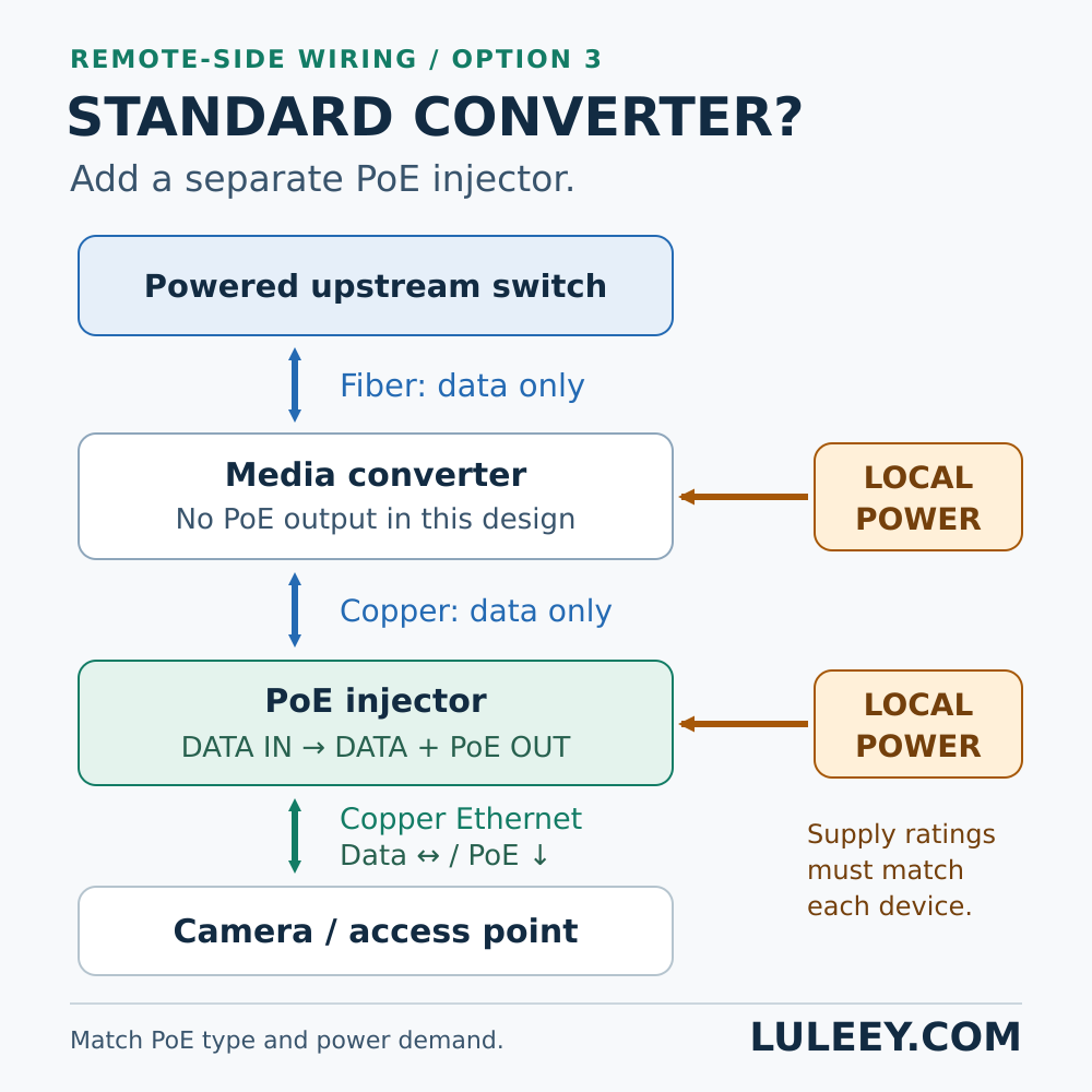
3. An ordinary media converter plus a PoE injector
If the converter has no PoE output, use this remote-side sequence:
Fiber → powered media converter → injector DATA IN → injector DATA + PoE OUT → compatible camera/AP.
Power the converter and injector according to their separate input specifications. Do not assume that one adapter can safely supply both.
The injector must support the device’s PoE requirements and the intended Ethernet data rate. Check the complete copper channel through the injector, including patch leads; do not assume that inserting an injector resets the cable-length allowance.
Check Power Before Choosing the Fiber Hardware
Use the exact camera or AP data sheet, not just the word “PoE.” Record the required IEEE type/class and maximum demand with relevant features enabled.
For example, IEEE 802.3at Type 2 distinguishes 30 W at the PSE from 25.5 W available at the PD under its specified conditions. A “30 W port” is not a promise of 30 W at the camera. The Ethernet Alliance technical brief documents this distinction.
For several devices, use LuLeey’s PoE power-budget calculation guide to check the shared budget. Keep camera input watts, switch allocations and the switch’s own supply requirements separate.
Do not substitute an unspecified passive-PoE supply for a standards-based injector. If a device requires a proprietary arrangement, verify its voltage, pin assignment and approved supply directly with its manufacturer.
If there is no suitable power at the remote site, resolve that first. A properly designed separate power feed or battery/solar system may be an option, but an ordinary fiber converter does not create electrical power from the network signal. Hybrid fiber-and-power cable uses separate conductors for electricity; it is not electrical PoE traveling through the glass.
Check Data Rate, Optical Compatibility and Distance
Power capability and data capability are independent. A device can receive enough power while its network connection remains slow or down.
For a conventional 100/1000BASE-T copper channel, the usual design limit is 100 m including patch cords, subject to the equipment and cabling specifications. The fiber section has its own reach and loss budget; do not apply the copper distance to the whole route or treat a fiber distance label as a power-delivery rating.
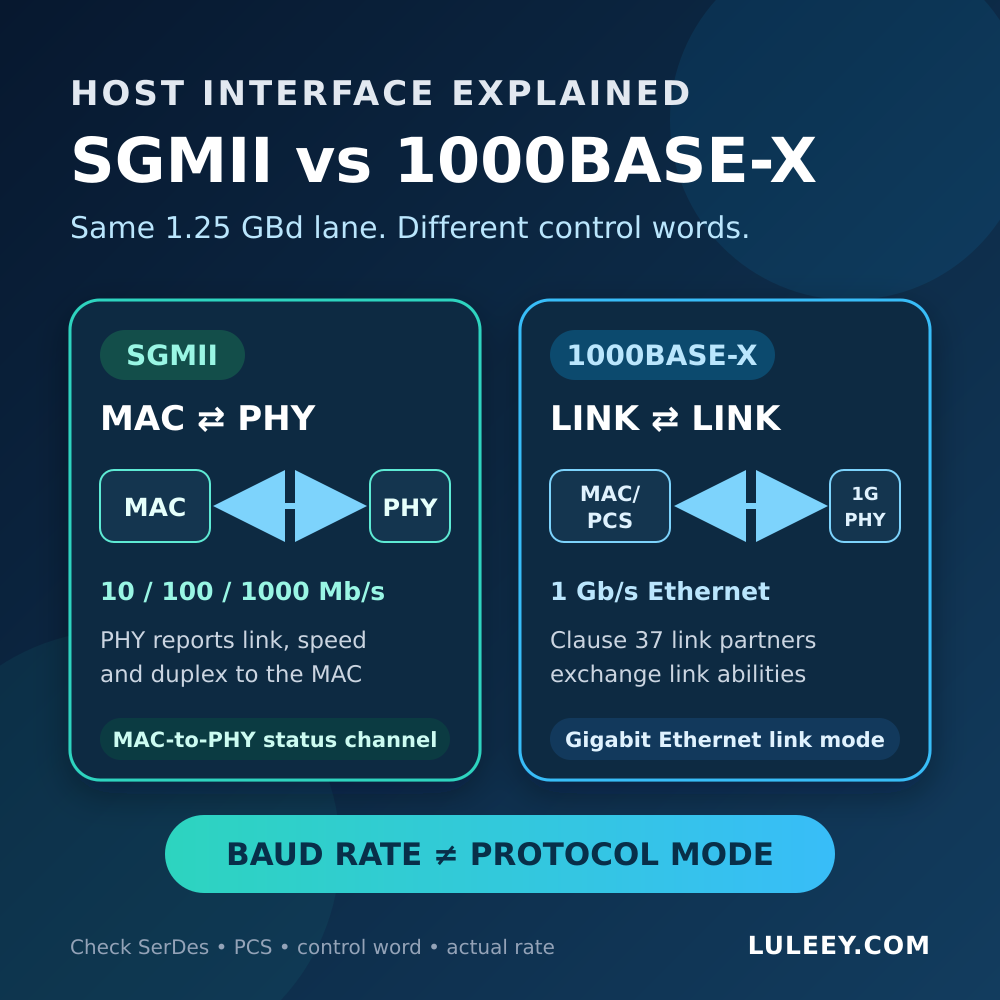
Verify both optical ends: Ethernet mode, fiber type, transmit/receive pairing, connector polish and receiver operating limits. For an SFP-based setup, distinguish physical fit, host SerDes mode, actual link rates and usable throughput. Check the exact host and module models, host chipset/PHY, firmware/driver, module coding and port settings. The SFP/SFP+ name alone does not settle compatibility.
For outdoor locations, confirm the enclosure, temperature range and approved power installation. Cable resistance and operating conditions matter to power delivery, as the IEEE practical PoE tutorial illustrates. Have the power installation and protection arrangements assessed by a qualified installer; a fiber link does not make the powered equipment weatherproof.
If the Camera Still Does Not Start
Work from the remote power source toward the device:
- Check the remote equipment supply. Is the converter or switch actually powered with the correct supply?
- Check the camera-facing port. Is it a PSE output, enabled and within budget? On an injector, distinguish DATA IN from DATA + PoE OUT.
- Check the device requirement. Compare its exact PoE type/class with the source; review any power-denied or overload indication.
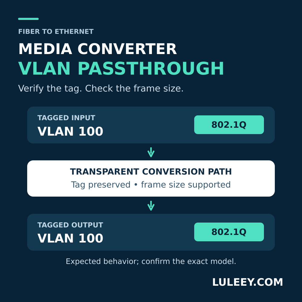
- Separate power from networking. If the camera boots but cannot be reached, check copper and optical link status, VLANs and IP settings. A powered camera does not prove a working fiber path.
Save the observed LEDs, port status and model numbers before changing anything. Test one change at a time in an approved maintenance window.
Where LuLeey Equipment Fits
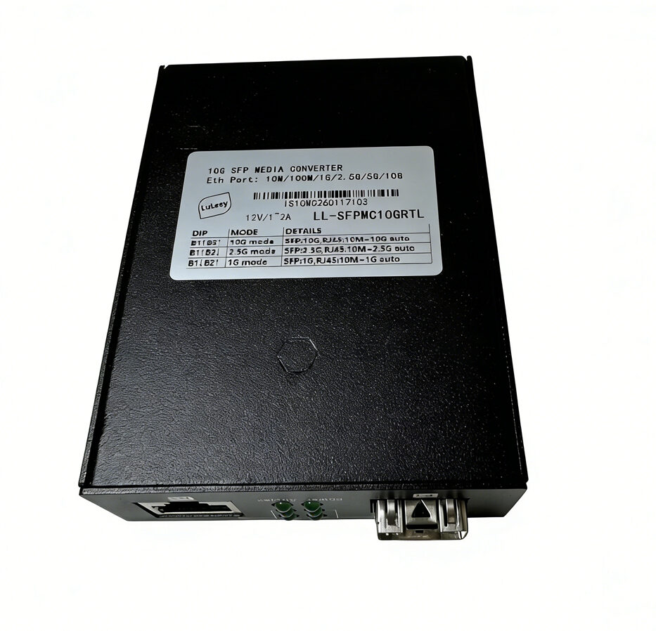
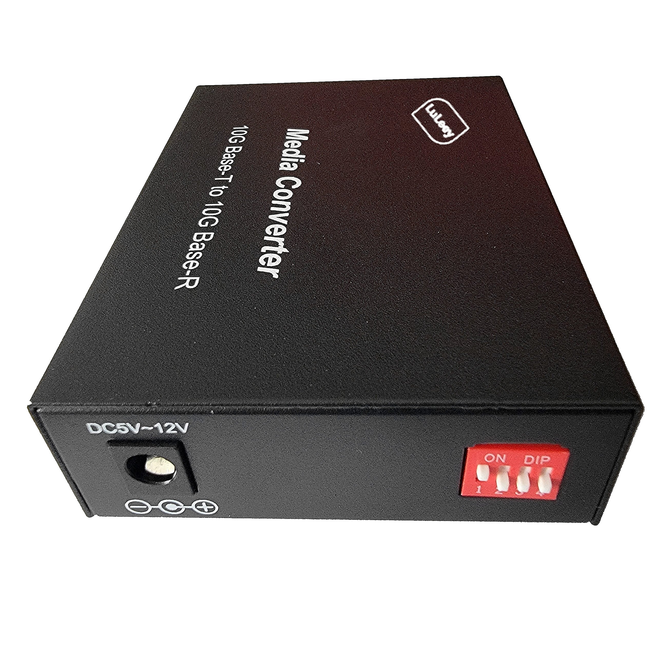
LuLeey’s copper-to-fiber media converter range is a starting point for the data-conversion section. Check each selected variant for an explicit PoE output specification; membership in this category is not proof of PSE capability.
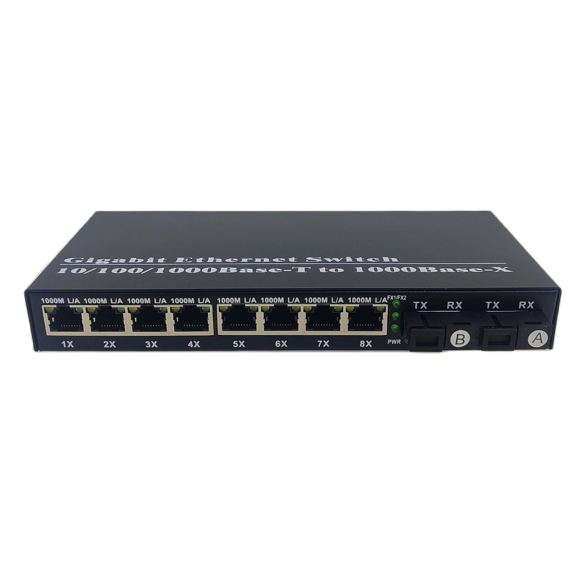
For a larger remote equipment room, the INS2M2GF26GT-24POE switch lists 24 IEEE 802.3af/at copper ports, two 1G SFP uplinks, up to 30 W per PoE port and a 400 W shared budget. It cannot deliver 30 W on all 24 ports simultaneously. Confirm the supply version and installation environment; this is not a recommendation for a single exposed camera pole.
Next step: send LuLeey the exact camera/AP models, device count, route lengths, existing fiber and remote power details. Review the data path and the power path together before choosing the converter, injector or switch.



 SFP/SFP+ (1G/2.5G/5G/10G)
 SFP-T (1G/2.5G/10G)
 AOC Cable 10G/25G/40G/100G
 DAC Cable 10G/25G/40G/100G
 QSFP28 QSFP+ SFP28 100G/40G/25G
 Copper to Fiber Media Converters
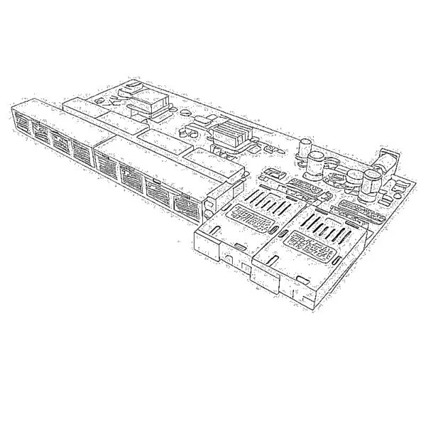 Fiber Media Converter PCBA Board
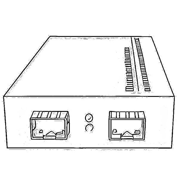 OEO Fiber Media Converters
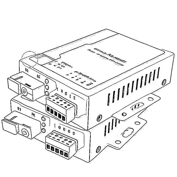 Serial to Fiber Media Converters
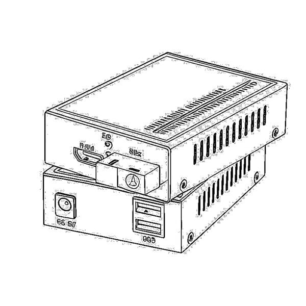 Video to Fiber Media Converters
 1000M GPON/EPON ONU
 10G EPON ONU/XG-PON/XGS-PON
 2.5G GPON/XPON STICK SFP ONU
 POE GPON/EPON ONU
 Wireless GPON/EPON ONT
 EPON OLT
 GPON OLT
 SFP PON Module
 Industrial Switches
 Managed Switches
 POE Switches
 Unmanaged Switches
 MTP/MPO Fiber Cables
 Fiber Optic Cassettes
 Fiber Optic Loopback
 Optic Cables and Fiber Pigtails
 Optical Splitters and Splitter Box
 Fiber Flange Connectors
 Optical Adapters
 Optical Attenuator
 Quick Connector and Connector Panel
 CATV Amplifier
 CATV Optical Receiver
 Visual Fault Locator
 OTDR
 Optical Power Meter
 Fiber Optic Identifier
 Fiber Optic Cleaners
 Fiber Cleavers & Fiber Strippers
 Copper Tools