Customs duties are the responsibility of customers, but standard logistics support DDP to most countries, duty-free such as US, DE, UK, CA, FR, IT, PL, AT, JP…





















































10GBase-T SFP+ Link Flapping means the physical link repeatedly changes between up and down. It may work for a few minutes, disconnect, reconnect and repeat. The cause can be a marginal copper channel, heat, insufficient host power, a host-side SerDes mismatch, unsupported module coding, firmware behavior or failed copper-side negotiation.
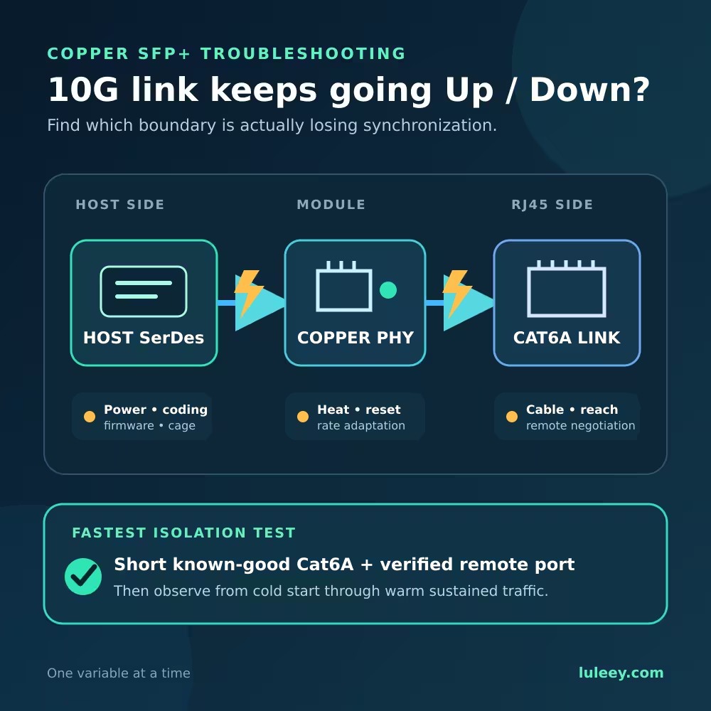
Do not replace the module immediately. First determine which side of the module is failing. A Copper SFP+ has a host-facing electrical interface inside the SFP+ cage and a separate twisted-pair Ethernet interface at the RJ45 connector. Either side can lose synchronization.
The fastest isolation test is to use a known-good short Cat6A cable and a verified remote port, then watch the link from a cold start through thermal stabilization. If that setup is stable, move outward one variable at a time.
10GBASE-T SFP+ Link Flapping: Quick Diagnosis
| What you observe | More likely area | First useful test |
|---|---|---|
| Module disappears and reappears in the host | Seating, host power, cage, firmware or coding | Reseat safely, inspect host logs and test a supported cage |
| Module stays detected but RJ45 link cycles | Cable, remote port, copper negotiation or module PHY | Use a short certified Cat6A cable and verified remote port |
| Stable when cold, unstable after warming | Thermal margin, airflow or host power | Record temperature and errors from startup |
| Stable at 2.5G or 5G but unstable at 10G | 10G cable margin, module reach or capability | Certify the channel and verify the exact 10G mode |
| Stable in one SFP+ cage but not another | Port configuration, cooling, power or hardware | Compare port settings and change one variable |
| Link remains up but throughput collapses | Errors, rate adaptation, flow control or endpoints | Check link-state logs, counters and both interface rates |
| Flapping began after an update | Firmware, driver, coding policy or changed defaults | Review the update and last authorized configuration |
This table narrows the fault domain. It does not prove the cause by itself.
First Confirm That It Is Really Link Flapping
Three symptoms are often mixed together.
Physical link flapping
The interface state changes from up to down and back again. Switch logs normally show repeated link-state events. Auto-negotiation or link startup runs again after the loss.
Stable link at a lower rate
The link remains up but negotiates at 5G, 2.5G or 1G instead of 10G. This is a rate or channel-capability issue, not flapping unless the link state also cycles.
Packet loss with the link still up
The carrier remains established, but traffic has errors, pauses or poor throughput. Investigate physical error counters, rate adaptation, congestion, flow control, drivers and endpoints before calling it a link flap.
Write down the exact symptom. “The Internet drops” is not enough because routing, DHCP, PPPoE, DNS or Wi-Fi can fail while the 10G physical link remains healthy.
Why a Copper SFP+ Has Two Compatibility Boundaries
The module sits between two different paths:
Host ASIC/SerDes → SFP+ electrical interface → copper PHY inside module → RJ45 cable → remote PHY
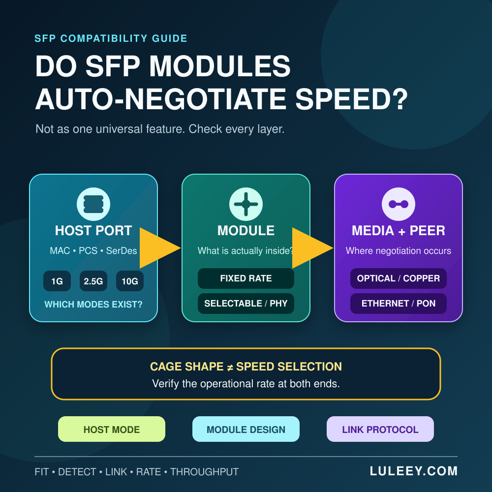
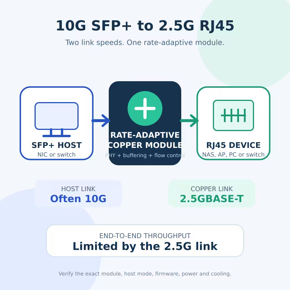
The host-facing side may use a fixed 10G electrical link while the RJ45 side negotiates 10G, 5G, 2.5G or 1G. Some modules perform rate adaptation internally. Other combinations require a different host mode or do not support the requested rate.
Verify:
- Physical SFP+ cage fit
- Host SerDes mode
- Module host mode
- Copper-side advertised rates
- Internal rate-adaptation behavior
- Firmware and driver support
- Module coding acceptance
- Actual negotiated rate
- Maximum usable throughput
LuLeey’s guide Can a 10G SFP+ Port Connect to 2.5G RJ45? explains why the host-facing rate and RJ45 rate may differ.
If the host can read the module EEPROM, that only proves the low-speed management interface is responding. It does not prove that the high-speed SerDes path or copper link is working.
Cause 1: A Marginal Copper Channel
10GBASE-T places much greater demands on twisted-pair cabling than 1G Ethernet. IEEE 802.3an specifies 10GBASE-T over balanced twisted-pair structured cabling for distances up to 100m. Achieving that result requires a compliant channel, not merely a cable jacket marked with a category.
Common problems include:
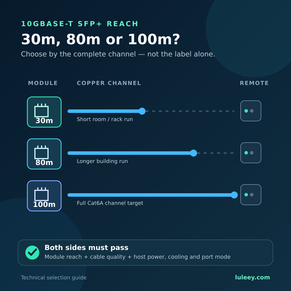
- Total channel length beyond the module’s 30m, 80m or 100m rating
- Category 6 used too far for reliable 10G operation
- Weak patch cords or mixed-category components
- Excessive pair untwisting at plugs or jacks
- Poor field terminations
- Crushed cable or tight bends
- Damaged contacts
- Excessive alien crosstalk
- Extra couplers and patch-panel connections
The Ethernet Alliance summarizes 10GBASE-T targets as up to 55m for Category 6 and up to 100m for Category 6A, 7 or 7A. The Cat6 figure still depends on installation conditions.
Start with a known-good short Cat6A patch cable. If the link becomes stable, the original channel, distance or termination requires investigation.
References: IEEE 802.3an-2006 and Ethernet Alliance: 10GBASE-T Revamped.
Cause 2: Heat and Insufficient Airflow
An active 10GBASE-T SFP+ contains a copper PHY and signal-processing circuitry inside a small enclosure. Temperature is influenced by module power, cable length, negotiated speed, chassis design, adjacent modules, airflow and ambient temperature.
A thermal problem is more likely when:
- The link is stable after startup but begins flapping later.
- Several adjacent copper modules are active.
- The same module is stable in a better-ventilated host.
- Temperature alarms occur near the failure.
- Manufacturer-approved airflow removes the problem.
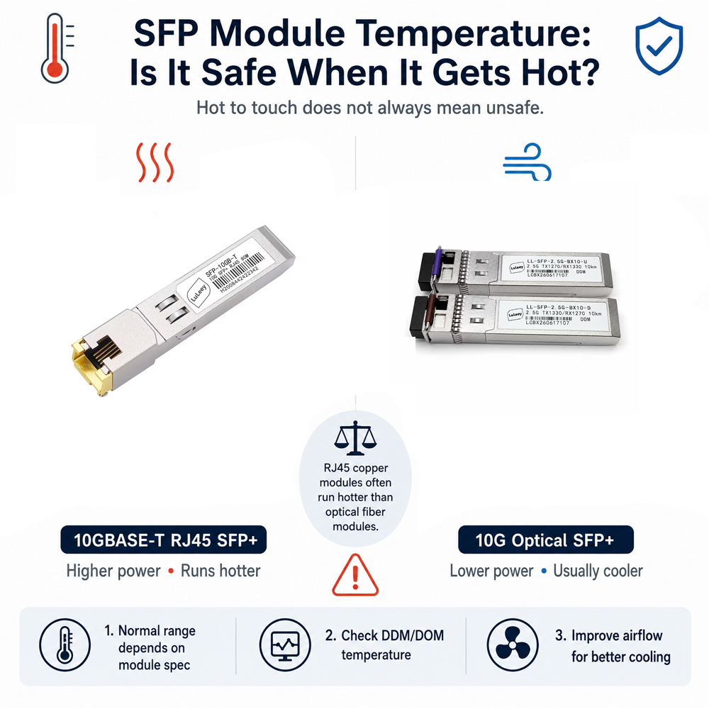
Do not diagnose overheating from touch alone. A metal module can feel uncomfortably hot while operating normally. Compare reported temperature with the exact specifications and correlate it with link events and errors.
LuLeey’s SFP Module Temperature guide provides a separate temperature-check workflow.
Do not attach an improvised heatsink that blocks the latch, touches neighboring ports or interferes with airflow.
Cause 3: Host Power or Power-Class Handling
Physical fit does not prove that an SFP+ host can supply and cool the selected copper module.
The current SNIA SFF-8419 specification defines SFP+ host/module power behavior. Modules begin in the default power condition, and a host can enable supported higher power classes. Power-supply and case-temperature requirements are part of the interface.
Possible symptoms of inadequate power support include:
- Failure to initialize
- Module resets
- Intermittent host detection
- Link failure under changing conditions
- Host warnings or port shutdown
Check the host’s supported module power, firmware and port restrictions. Some compact devices may support only a limited number of active copper modules or specify particular cages.
Official reference: SNIA SFF-8419.
Cause 4: Rate Negotiation or Rate Adaptation Mismatch
On the RJ45 side, the module and remote PHY advertise and select supported Ethernet modes. The host-side SFP+ link may follow a different rule.
For example, the remote device may negotiate 2.5G while the host-facing link remains at 10G through internal rate adaptation. That works only when the module implements the required function and the host accepts its behavior.
| Layer | Question to answer |
|---|---|
| Host cage | Which SerDes modes does the exact port support? |
| Module | Does this variant use a fixed or multi-rate host mode? |
| Copper PHY | Which RJ45 rates are advertised and negotiated? |
| Rate adaptation | How are unequal host and copper rates handled? |
| Result | What is the stable rate and maximum usable throughput? |
Do not force mismatched settings at opposite ends. Record the working auto-negotiation state first, then test only combinations supported by both devices.
Cause 5: Module Coding, Firmware or Driver Policy
A host can accept a module mechanically but reject its identification, limit its features or change behavior after a firmware update.
Look for:
- Unsupported-transceiver messages
- Port-disabled or high-power-denied events
- Module resets in system logs
- Changed speed defaults after an update
- Firmware releases mentioning SFP, PHY or negotiation behavior
- A module working in one host family but not another
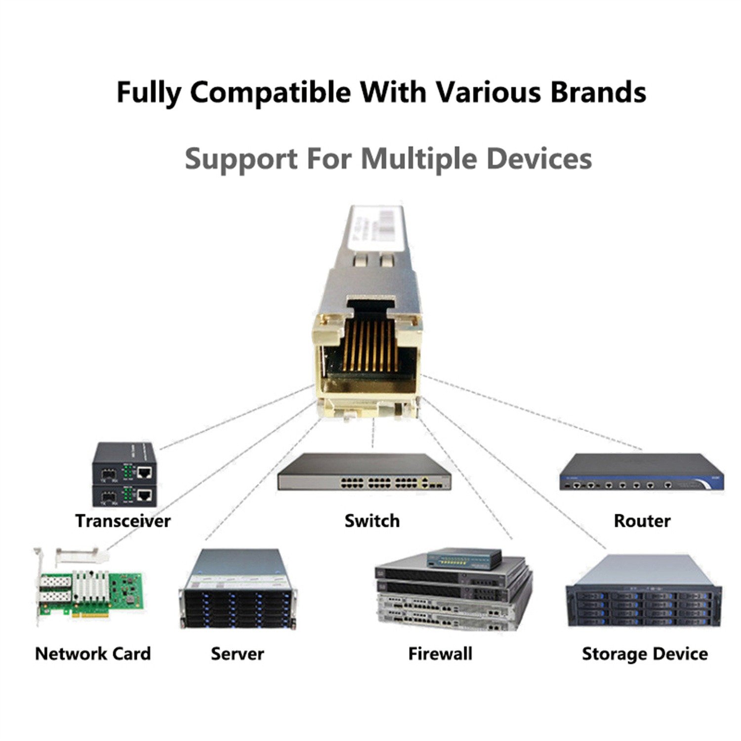
Use coding intended for the exact host when required. “Compatible with a brand” is less precise than an exact model, hardware revision and firmware combination.
Cause 6: Poorly Seated or Damaged Electrical Contacts
An RJ45 copper module has two electrical connector systems:
- The module card edge inside the SFP+ cage
- The RJ45 contacts at the copper interface
A partially latched module, contaminated cage, damaged plug or worn port can create intermittent behavior.
Follow the host’s approved hot-plug procedure. Inspect the module and cable for damage, confirm the latch is fully engaged, and test a known-good cable. Do not insert liquids or abrasive tools into the cage.
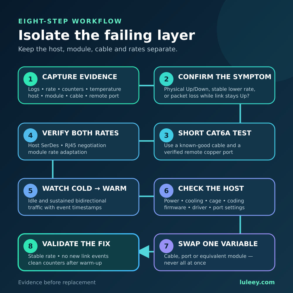
An Eight-Step Troubleshooting Workflow
Step 1: Capture evidence
Record:
- Exact module variant and coding
- Host model, revision, firmware and driver
- Port number
- Remote device and port
- Cable category and full channel length
- RJ45 negotiated rate
- Host-side port mode
- Up/down timestamps
- Available temperature readings
- Physical error counters
Step 2: Separate the physical link from the application
Confirm whether the interface state actually changes. If it stays up, troubleshoot packet loss, routing or endpoints as a different problem.
Step 3: Test a short known-good Cat6A cable
Use a verified remote port while keeping the same host, module and target rate. Stability points toward the installed channel.
Step 4: Verify both interface rates
Confirm host SerDes, module host mode, copper advertisement, remote capability and rate adaptation.
Step 5: Observe cold-to-warm operation
Log temperature, link state and errors over time. Repeat under sustained bidirectional traffic.
Step 6: Check host support
Review host power, cooling, coding, firmware, driver and cage restrictions.
Step 7: Swap one controlled variable
Change only one item at a time:
- Cable
- Remote port
- SFP+ cage
- Equivalent known-good module
- Authorized firmware or configuration
Step 8: Validate the repair
Run sustained bidirectional traffic, monitor physical counters, confirm the rate, and check for new link events after thermal stabilization.
When Should You Replace or Return the Module?
Replacement becomes reasonable when:
- The same module fails in multiple verified supported hosts.
- A known-good equivalent remains stable in the same cage and channel.
- The suspect module resets while host power remains stable.
- The failure follows the module between supported ports.
- Visible damage, abnormal odor or discoloration is present.
- It fails the seller’s documented test conditions.
Stop using the module immediately if there is smoke, a burning smell, severe discoloration or host electrical-protection events.
Do not return a module solely because the installed cable is unstable while a verified short channel works. That evidence points first to channel quality or distance.
Applying the Workflow to LuLeey Modules
LuLeey’s 10GBASE-T SFP+ to RJ45 product page lists 30m, 80m and 100m distance/chip options, Cat6A/Cat7 cabling, multi-rate operation and DDM support.
The page now publishes power measurements and states that power depends on the chip, cable length and cable quality:
| LuLeey page measurement | 30m cable | 80m cable | 100m cable |
|---|---|---|---|
| Marvell CUX3610 | 1.45W | 1.50W | 1.65W |
| Broadcom BCM84891L | 1.49W | 1.88W | 1.92W |
These are LuLeey product-page measurements, not universal chipset specifications. The page does not state every reproducibility detail, such as host model, ambient temperature, traffic state and measurement uncertainty.
Before requesting support, provide:
- Exact chip and distance option
- Host and remote-device models
- Firmware and driver versions
- Cable length and category
- Negotiated rate before each drop
- Link-event timestamps and counters
- Available module and chassis temperatures
- Result of a short Cat6A test
Final Answer
To fix 10GBASE-T SFP+ link flapping, isolate the two sides of the module.
First verify that the physical link really cycles. Test the RJ45 side with a known-good short Cat6A cable and verified remote port. Then confirm the host SerDes mode, rate adaptation, firmware, coding, power allowance and airflow.
Monitor the link from cold startup through sustained traffic, changing one variable at a time. Replace the module when the failure follows it across verified supported hosts and channels—not simply because the first installation is unstable.
 SFP/SFP+ (1G/2.5G/5G/10G)
 SFP-T (1G/2.5G/10G)
 AOC Cable 10G/25G/40G/100G
 DAC Cable 10G/25G/40G/100G
 QSFP28 QSFP+ SFP28 100G/40G/25G
 Copper to Fiber Media Converters
 Fiber Media Converter PCBA Board
 OEO Fiber Media Converters
 Serial to Fiber Media Converters
 Video to Fiber Media Converters
 1000M GPON/EPON ONU
 10G EPON ONU/XG-PON/XGS-PON
 2.5G GPON/XPON STICK SFP ONU
 POE GPON/EPON ONU
 Wireless GPON/EPON ONT
 EPON OLT
 GPON OLT
 SFP PON Module
 Industrial Switches
 Managed Switches
 POE Switches
 Unmanaged Switches
 MTP/MPO Fiber Cables
 Fiber Optic Cassettes
 Fiber Optic Loopback
 Optic Cables and Fiber Pigtails
 Optical Splitters and Splitter Box
 Fiber Flange Connectors
 Optical Adapters
 Optical Attenuator
 Quick Connector and Connector Panel
 CATV Amplifier
 CATV Optical Receiver
 Visual Fault Locator
 OTDR
OTDR Optical Power Meter
 Fiber Optic Identifier
 Fiber Optic Cleaners
 Fiber Cleavers & Fiber Strippers
 Copper Tools


